
Catalog excerpts
Implants trauma Distal Anterolateral Tibia Locking Plate
Open the catalog to page 1
CAUTION: Federal Law (USA) restricts this device to sale by or on the order of a board certified physician. WARNING: If there is no sufficient bone healing, wrong or incomplete postoperative care, plate might break. All ITS plates are preformed anatomically as a matter of principle. If adjustment of the plate to the shape of the bone is required, this is possible by carefully bending gently in one direction once. Particular care is required when bending in the region of a plate hole, as deformation of the plate may lead to a failure of the locking mechanism. The plate must not be buckled or...
Open the catalog to page 2
1. Introduction P. 5 Preface P. 6 Screws P. 7 Properties P. 8 Indications & Contraindications P. 8 Time of operation 2. Surgical Technique P. 10 Pre-operative patient preparation P. 10 Access P. 11 Reduction P. 12 Placement of the screws P. 16 Postoperative treatment P. 16 Explantation 3. Information P. 17 Notes P. 19 Locking P. 19 Dotize® P. 20 Order list P. 22 Reconditioning Manual
Open the catalog to page 3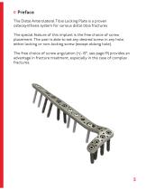
Preface The Distal Anterolateral Tibia Locking Plate is a proven osteosynthesis system for various distal tibia fractures. The special feature of this implant is the free choice of screw placement. The user is able to set any desired screw in any hole, either locking or non-locking screw (except oblong hole). The free choice of screw angulation (+/- 15°, see page 19) provides an advantage in fracture treatment, especially in the case of complex fractures.
Open the catalog to page 5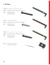
Cortical Screw, locking, D=3.5mm, SH Spiral Drill, D=2.7mm, L=100mm, AO Connector Screwdriver, WS 2.5, self-holding sleeve Spiral Drill, D=2.7mm, L=100mm, AO Connector Screwdriver, WS 2.5, self-holding sleeve Cancellous Screw, locking, D=4.2mm, SH Spiral Drill, D=2.5mm, L=180mm, AO Connector Screwdriver, WS 2.5, self-holding sleeve Guide Wire, Steel, D=1.6mm, L=150mm, TR, w. thread
Open the catalog to page 6
Properties Properties of the implant: • Plate material: Titanium • Material of screws: TiAl6V4 ELI • Easier removal of the implant after the fracture has healed • Improved fatigue strength of the implant • Reduced risk of cold welding • Reduced risk of inflammation and allergy • Multi-directional locking • Anatomically shaped • Torsion and contour of the plate shaft has been adapted to that of the distal tibia • 4 distal plate holes for fixation close to joint • Oblong hole for optimal positioning and alignment of the tibia length • Pointed proximal plate end for percutaneous insertion •...
Open the catalog to page 7
Indications, Contraindications & Time of operation Indications: • Extra- and intra-articular fractures of the distal tibia • Distal tibia fractures also in combination with diaphyseal fractures Existing infections in the fracture zone and operation area Common situations that do not allow osteosynthesis With advanced osteoporosis In cases of skin and soft tissue problems that prevent a tension-free skin closure Obesity Lack of patient compliance Time of operation: • Immediately after trauma or delayed
Open the catalog to page 8
Surgical Technique
Open the catalog to page 9
Pre-operative patient preparation • General anaesthesia, local anaesthesia or combination can be used • The patient is in the supine position with the leg raised slightly on a pedestal • Application of a tourniquet Access Anterior approach: • Skin incision along the middle line of the upper ankle joint with the center over the joint • The incision should be made 1 to 2cm away from the fracture to avoid suture placement directly above the plate • Separation of the superficial and deep fascia giving due attention to the superficial peroneal nerve • The tendon of the tibialis anterior muscle...
Open the catalog to page 10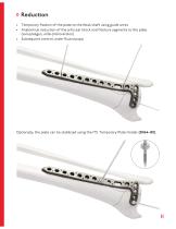
Reduction • Temporary fixation of the plate to the tibial shaft using guide wires • Anatomical reduction of the articular block and fracture segments to the plate (varus/valgus, ante-/retroversion) • Subsequent control under fluoroscopy Optionally, the plate can be stabilized using the ITS. Temporary Plate Holder (58164-150).
Open the catalog to page 11
Placement of the screws With the spiral drill, D=2.7mm, L=100mm, AO Connector (61273-100), drill through the drill guide, D=2.7/2.0mm (62202) into the oblong hole. Determine appropriate length using the depth gauge, solid small fragment screws (59022). Insert the D=3.5mm cortical screw (32351-XX) with the screwdriver, WS 2.5, self-holding sleeve (56252). Advice: For optimal alignment of the plate with tibia length, we recommend to first fill the oblong hole.
Open the catalog to page 12
Then, using the spiral drill, D=2.5mm, L=100mm, AO Connector (61253-100), drill through the drill guide, D=2.7/2.0mm (62202) into a distal plate hole. Determine appropriate length using the depth gauge, solid small fragment screws (59022). Insert the D=4.2mm locking cancellous screw (37422-XX-N) with the screwdriver, WS 2.5, self-holding sleeve (56252).
Open the catalog to page 13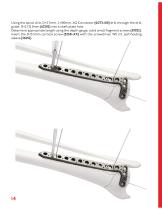
Using the spiral drill, D=2.7mm, L=100mm, AO Connector (61273-100) drill through the drill guide, D=2.7/2.0mm (62202) into a shaft plate hole. Determine appropriate length using the depth gauge, solid small fragment screws (59022). Insert the D=3.5mm cortical screw (32351-XX) with the screwdriver, WS 2.5, self-holding sleeve (56252).
Open the catalog to page 14
The remaining plate holes are then filled, with either locking or non-locking screws. Subsequent control of plate position under fluoroscopy.
Open the catalog to page 15
Postoperative treatment • Keep leg raised for 2 to 5 days and take decongestant actions • Physical therapy immediately following surgery (no immobilization required) • Partial toe touch weight-bearing - at week 6-8 (depends on wound healing): 22-33 lbs • Full weight-bearing - after about 3 months (depends on consolidation of the joint) • When a locking screw connection has been used, it is necessary to be aware that the diagnosis of a non-union may be very delayed. Explantation If desired by the patient, the implant can be removed. Removal should be performed at the earliest 1 1/2 years...
Open the catalog to page 16All I.T.S. catalogs and technical brochures
-
 ufs
ufs1 Pages
-
 DHL
DHL2 Pages
-
 ITS
ITS2 Pages
-
 PHL
PHL24 Pages
-
 ACLS
ACLS20 Pages
-
 CFN
CFN32 Pages
-
 OLS
OLS24 Pages
-
 PHLs
PHLs20 Pages
-
 CTN - Cannulated Tibia Nail
28 Pages
-
 SR Sacral Rods
20 Pages
-
 HCS
HCS24 Pages
-
 TOS Twist-Off Screw
20 Pages
-
 TLS
TLS20 Pages
-
 PRS-RX
32 Pages
-
 HLS
HLS20 Pages
-
 ES
ES20 Pages
-
 SR
SR20 Pages
-
 FL
FL24 Pages
-
 PL - Pilon Locking Plate small
12 Pages
-
 OL - Olecranon Locking Plate
24 Pages
-
 CAS
CAS40 Pages
-
 FCN
FCN20 Pages
-
 HOL
HOL24 Pages
-
 FLS
FLS24 Pages
-
 PFL
PFL20 Pages
-
 HTO
HTO24 Pages
-
 PTL
PTL32 Pages
-
 DFL
DFL32 Pages
-
 SCL
SCL32 Pages
-
 SLS
SLS24 Pages
-
 CAL
CAL20 Pages
-
 DUL
DUL24 Pages
-
 CLS
CLS28 Pages


