
Catalog excerpts

Implants trauma Fibula Locking Plate
Open the catalog to page 1
All ITS plates are preformed anatomically as a matter of principle. If adjustment of the plate to the shape of the bone is required, this is possible by carefully bending gently in one direction once. Particular care is required when bending in the region of a plate hole, as deformation of the plate may lead to a failure of the locking mechanism. The plate must not be buckled or bent several times. This is particularly important in the case of titanium implants, to prevent material fatigue and subsequent failure. The method of bending is the conscious responsibility of the operating doctor;...
Open the catalog to page 2
1. Introduction P. 5 Preface P. 6 Screws P. 7 Properties P. 8 Indications & Contraindications P. 8 Time of operation 2. Surgical Technique P. 10 Pre-operative patient preparation P. 10 Access P. 10 Reduction P. 11 Placement of the screws P. 15 Postoperative treatment P. 15 Explantation 3. Information P. 17 Locking P. 17 Dotize® P. 18 Order list P. 20 Reconditioning Manual P. 22 Notes
Open the catalog to page 3
Preface The Fibula Locking Plate is a proven osteosynthesis system for various distal fibula fractures. The special feature of this implant is the free choice of screw placement. The user is able to set any desired screw in any hole, either locking or non-locking screw (except oblong hole). The free choice of screw angulation (+/- 15°, see page 17) provides an advantage in fracture treatment, especially in the case of complex fractures.
Open the catalog to page 5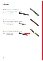
Cortical Screw, locking, D=3.5mm, SH Spiral Drill, D=2.7mm, L=100mm, AO Connector Screwdriver, WS 2.5, self-holding sleeve Spiral Drill, D=2.7mm, L=100mm, AO Connector Screwdriver, WS 2.5, self-holding sleeve Cancellous Screw, locking, D=3.5mm, SH Spiral Drill, D=2.0mm, L=100mm, AO Connector Screwdriver, WS 2.5, self-holding sleeve
Open the catalog to page 6
Properties Properties of the implant: • Plate material: Titanium • Material of screws: TiAl6V4 ELI • Easier removal of the implant after the fracture has healed • Improved fatigue strength of the implant • Reduced risk of cold welding • Reduced risk of inflammation and allergy • Multi-directional Locking • Anatomically shaped • Oblong-hole for optimal positioning and alignment of the fibula length • Pointed proximal plate end for percutaneous insertion • Left/right version • Plate lengths: 4, 6, 8, 10, 12-hole
Open the catalog to page 7
Indications, Contraindications & Time of operation Indications: • Dislocated ankle-fractures group B+C according to Weber (with or without comminuted zones) Existing infections in the fracture zone and operation area Common situations that do not allow osteosynthesis With advanced osteoporosis In cases of skin and soft tissue problems that prevent a tension-free skin closure Obesity Lack of patient compliance Time of operation: • Immediately after injury • After regression of the swelling
Open the catalog to page 8
Surgical Technique
Open the catalog to page 9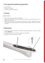
Pre-operative patient preparation • Supine position • Primary Tourniquet • General or regional anesthesia Access Lateral access: • Skin incision above the centre of the fibula • The incision should be made 1-2cm away from the fracture so that the suture is not directly over the plate • After incision of the inferior extensor retinaculum (cruciform ligament) directly in front of the fibula the toe extensors and the variable peroneus tertius are retracted forwards 1 Reduction • Temporary fixation of the plate to the fibula shaft using forceps or temporary plate holder (58164-150) • Anatomical...
Open the catalog to page 10
Placement of the screws With the spiral drill, D=2.7mm, L=100mm, AO Connector (61273-100), drill through the drill giude, D=2.7/2.0mm (62202) into the long-hole. Determine appropriate length using the depth gauge, solid small fragment screws (59022). Insert the D=3.5mm cortical screw (32351-XX) with the screwdriver, WS 2.5, self-holding sleeve (56252). Advice: For optimal alignment of the plate with fibula length, we recommend to first occupy the oblong hole.
Open the catalog to page 11
Then using the spiral drill, D=2.5mm, L=100mm, AO Connector (61253-100) to drill through the drill guide, D=2.7/2.0mm (62202) into a distal plate hole. Determine appropriate length using the depth gauge, solid small fragment screws (59022). Insert the D=3.5mm locking cortical screw (37351-XX-N) with the screwdriver, WS 2.5, selfholding sleeve (56252).
Open the catalog to page 12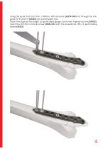
Using the spiral drill, D=2.7mm, L=100mm, AO Connector (61273-100) drill through the drill guide, D=2.7/2.0mm (62202) into a shaft plate hole. Determine appropriate length using the depth gauge, solid small fragment screws (59022). Insert the D=3.5mm cortical screw (32351-XX) with the screwdriver, WS 2.5, self-holding sleeve (56252).
Open the catalog to page 13
The remaining plate holes are then filled, with either locking or non-locking screws. Subsequent control of plate position under fluoroscopy.
Open the catalog to page 14
Postoperative treatment • Splinted shank for 2 weeks • Physical therapy • 6-8 weeks rest • When a locking screw connection has been used, it is necessary to be aware that the diagnosis of a non-union may be very delayed. Explantation If desired by the patient, the implant can be removed. Removal should be performed at the earliest 6 months - 1 1/2 years later or after radiographic verification of the healed bone. The problem of cold welding was resolved by using a special surface treatment (for further information see page 17).
Open the catalog to page 15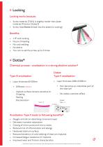
Locking Locking works because: • Screw material (TiAlV) is slightly harder than plate material (Titanium Grade 2) • Screw head forms thread into the plate (no cutting) ± 15° and Locking No pre threading No cold welding No debris You can re-set the screw up to 3 times Dotize® Chemical process - anodization in a strong alkaline solution* Dotize Type II anodization • Layer thickness 2000-10 000nm + Film becomes an interstitial part of the titanium + Different colors - Implant surface remains sensitive to: Chipping Peeling Discoloration - No visible cosmetic effect Dotize® Type - II Anodization...
Open the catalog to page 17All I.T.S. catalogs and technical brochures
-
 ufs
ufs1 Pages
-
 DHL
DHL2 Pages
-
 ITS
ITS2 Pages
-
 PHL
PHL24 Pages
-
 ACLS
ACLS20 Pages
-
 CFN
CFN32 Pages
-
 OLS
OLS24 Pages
-
 PHLs
PHLs20 Pages
-
 CTN - Cannulated Tibia Nail
28 Pages
-
 SR Sacral Rods
20 Pages
-
 HCS
HCS24 Pages
-
 TOS Twist-Off Screw
20 Pages
-
 TLS
TLS20 Pages
-
 PRS-RX
32 Pages
-
 HLS
HLS20 Pages
-
 ES
ES20 Pages
-
 SR
SR20 Pages
-
 PL - Pilon Locking Plate small
12 Pages
-
 OL - Olecranon Locking Plate
24 Pages
-
 CAS
CAS40 Pages
-
 FCN
FCN20 Pages
-
 HOL
HOL24 Pages
-
 FLS
FLS24 Pages
-
 PFL
PFL20 Pages
-
 DTL
DTL24 Pages
-
 HTO
HTO24 Pages
-
 PTL
PTL32 Pages
-
 DFL
DFL32 Pages
-
 SCL
SCL32 Pages
-
 SLS
SLS24 Pages
-
 CAL
CAL20 Pages
-
 DUL
DUL24 Pages
-
 CLS
CLS28 Pages


