Group: Varian Medical Systems

Catalog excerpts

PROTON BEAM THERAPY FACILITY Facility and Interface Requirements VARIAN PARTICLE THERAPY I FACILITY REQUIREMENTS
Open the catalog to page 1
Introduction The ProBeam™ proton therapy system from Varian Medical Systems must be installed in a building that meets Varian requirements and conforms to local regulations, especially regulations on radiation safety. Although the design and building of the facility are the customer’s responsibility, Varian will provide ongoing support to assist with the process. Varian’s proposal will be based on the following assumptions: • Varian will provide regular on-site support in order to assist with the building design and design approval, as well as to minimize delays. • The customer’s building...
Open the catalog to page 4
Facility design and radiation protection The architectural design of the proton therapy facility is driven by clinical requirements such as the number and type of treatment rooms; the resulting radiation shielding layout necessary to protect personnel, patients and the public; and the space allocation for clinical and technical areas. The proposed building layout is based on a modular concept: Customer requirements can be incorporated without changing the base allocation for technical areas needed for the proton therapy equipment. Treatment rooms and other clinical areas can be added...
Open the catalog to page 5
The standard Varian proton therapy system layout has been evaluated by several authorities and has been found to satisfy the respective local regulations. Therefore, the architect’s team can use the wall thicknesses in the standard layout as estimates until the customer’s radiation safety specialist provides final confirmation. Varian will support radiation shielding discussions by providing a standard set of documentation and input during meetings with the customer’s radiation safety specialist. Radiation protection equipment Typically, the BDCT is responsible for installing permanent...
Open the catalog to page 6
Shielding wall openings The beam transport system area requires a wall opening for inserting magnets and related beam transport and energy selection system equipment. The opening must have restricted access and should be thermally insulated. In addition, the cyclotron maze must have a removable section as indicated in Figure 1. Non-radiation areas Equipment will be inserted via normal doors, facade doors in the upper level, and elevators installed in the building. Doors or wall openings up to the full ceiling height must be provided in many areas for transport into the building. Door sills...
Open the catalog to page 7
Electrical rooms and control rooms All electrical rooms must be equipped with computer room floors. On the upper level, the load bearing capacity must be 50 kN/m2 (1,050 lbs/ft2). All cabinets require frames, some cabinets’ frames must support weights up to 5 metric tons. A detailed specification will be provided after contract approval. Building settlement Outside areas Ground reinforcements to install mobile cranes of up to 800 metric tons for rigging of heavy components will be provided by the customer, near the outside walls of the respective equipment room and near the entrance to the...
Open the catalog to page 8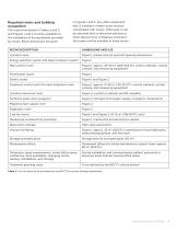
Required rooms and building occupation The rooms mentioned in Tables 2 and 3, and Figures 1 and 2 must be available for the installation of the equipment provided by Varian. Room dimensions are given in Figures 1 and 2. Any other equipment that is installed in these rooms must be coordinated with Varian. Otherwise, it will be assumed that no electrical cabinets or other devices from companies involved in the project will be installed in these rooms. Room description Cyclotron area Figure 1; please note pit and roof opening dimensions Energy selection system and beam transport system Main...
Open the catalog to page 9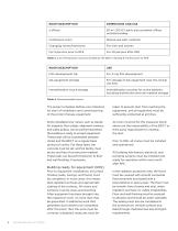
Room description 20 m2 (215 ft2) each; also container offices outside building Conference room Shared use with customer Changing rooms/restrooms Table 3. List of temporary rooms provided by the BDCT starting 6 months prior to RFE Room description For X-ray film development For storage of QA equipment near the clinical use area Immobilization couch storage Immobilization couches for active patients, including disinfection and raw material storage Table 4. Recommended rooms The project schedule defines one milestone for start of installation and commissioning of the proton therapy equipment:...
Open the catalog to page 10
The floors in the electrical rooms must be treated with a dust- and water-repellent coating. The coating must be sufficient to withstand installation of cable trays and double floors without degradation. An access floor (computer floor) must be installed in all electrical rooms. The floors, walls, and ceilings in all rooms in which the proton therapy equipment is installed must be dust- and water-repellent. The color white is recommended in order to allow contamination to be recognized more easily and to ensure better light conditions. At RFE HVAC, electrical supply, and cooling water,...
Open the catalog to page 11
of 28°C ±2°C. The cyclotron requires a temperature regulation with ±1°C temperature tolerance and a freely selected set-point selection between 30°C and 37°C for the supply water temperature. The table below explains this in more detail. The total load in this circuit will not exceed ~ 650 kW. 2. “Power Supply”: The RF amplifier, test load, and magnet power supply units are cooled with deionized water. The activation of the water in this circuit by neutrons is irrelevant. Supply temperature: 24°C. The total load in this circuit will not exceed ~ 490 kW. 3. “Cryogenics”: The helium...
Open the catalog to page 12
Humidity requirements: • All areas < 65%, non-condensing Compressed air (cooling room, workshops, electrical rooms) for operation of machine tools and cleaning • Additionally in electrical rooms noncondensing at 18ºC (64°F) Pressure: 5–6 bar, relative to the surrounding atmosphere A maximum of 200 kW of heat is estimated to be generated by the equipment (magnets and power supplies) which will be dissipated in the ambient air. During typical operation, Varian estimates that ≤100 kW is dissipated in the ambient air by heated equipment parts. Ventilation Varian recommends that all radiation...
Open the catalog to page 13All Varian Oncology catalogs and technical brochures
-
 Brachytherapy Applicator Catalog
150 Pages
-
 GammaMedplus™ iX Afterloader
4 Pages
-
 Trilogy Brochure
7 Pages
-
 VitalBeam
8 Pages
-
 HyperArc Overview
2 Pages
-
 TrueBeam Safety Features
2 Pages
-
 TrueBeam Brochure
11 Pages
-
 Eclipse™
2 Pages
-
 INTRACRANIAL SRS PACKAGE
4 Pages
-
 ProBeam 360
2 Pages
-
 VELOCITY SOFTWARE
3 Pages
-
 ProBeam Compact Brochure
9 Pages
-
 oNCOLOGY CARE MANAGEMENT
3 Pages
-
 360 ONCOLOGY
3 Pages
-
 Proton Therapy reatment
4 Pages
-
 HALCYON
12 Pages
-
 PaxScan ® 3030X
2 Pages
-
 PaxScan ® 4336X
4 Pages
-
 PaxScan ® 4343R
2 Pages
-
 Nexus-DRF™
2 Pages
-
 2520DX
2 Pages
-
 1515DXT
2 Pages
-
 PaxScan 1508 DXT
2 Pages
-
 PaxScan 1313DXT
2 Pages
-
 1308DXT
2 Pages
-
 Calypso Product Brief
2 Pages
-
 Clinac Brochure
12 Pages
-
 ProBeam Brochure
16 Pages
-
 Capri? Applicator Set
2 Pages
-
 Edge Brochure
22 Pages
-
 NDI-452
4 Pages
-
 M-101G
6 Pages
-
 M-105SP
6 Pages
-
 M-109
M-1096 Pages
-
 M-113
M-1136 Pages
-
 M-143
M-1436 Pages
-
 M-147SP
6 Pages
-
 M-146
M-1466 Pages
-
 M-147
M-1476 Pages
-
 RAD-85S
6 Pages
-
 M-149
M-1496 Pages
-
 M-151
M-15110 Pages
-
 M-152
M-15212 Pages
-
 M-153
M-1538 Pages
-
 PaxScan 3030+
2 Pages
-
 M-171
M-1716 Pages
-
 PaxScan 2520E+
2 Pages
-
 PaxScan 4030E
2 Pages
-
 PaxScan 4336R
2 Pages
-
 PaxScan® 2520XI/V
2 Pages
-
 PaxScan® 2520D/CL
2 Pages
-
 PaxScan® 2020X
2 Pages
-
 PaxScan® 2020+
2 Pages
-
 1313
13132 Pages
-
 PaxScan® 1308
2 Pages
-
 Vitesse 3.0
3 Pages
-
 BrachyVision
7 Pages
-
 RapidArc
8 Pages
-
 Varian Exact© IGRT couch
2 Pages
-
 ARIA Oncology Information System
12 Pages
-
 PaxScan ® 4030CB
2 Pages
-
 PaxScan ® 1508DXT
2 Pages
-
 PaxScan ® 1313DX
2 Pages
-
 PaxScan ® 1308DX
2 Pages
-
 Vitesse? 2.5
2 Pages
-
 VariSeed? 8.0 Brochure
7 Pages
-
 BrachyVision Acuros
3 Pages
-
 BrachyVision? 8.5
7 Pages
-
 Varian BrachyTherapy
147 Pages


