カタログの抜粋

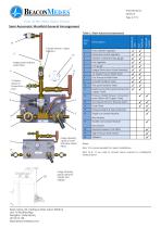
Semi Automatic and Manual Manifold Systems SPECIFICATION SEMI AUTOMATIC & MANUAL MANIFOLDS Semi Automatic Manifold Control Systems The BeaconMedæs Semi Auto Manifold is designed to supply piped medical gas where continuity of supply is essential, and where the gas is to be supplied from high pressure gas cylinders. All individual components conform to ISO and HTM requirements to form a medical gas control panel to which maximises safety requirements with simplified function. The Semi Automatic Manifold shall be supplied fully tested. All polymers and elastomers in the gas flow that can be subjected to working pressure greater than 3000 kPa shall be halogen-free. The use of PTFE, PCTFE, Viton and other halogenated polymers in these applications is strictly prohibited. Non-return valves fitted to header manifolds shall have a metallic seat with ceramic ball. Soft seat nonreturn valves utilising polymers or elastomers are not acceptable. The duty bank is determined by operating the right hand regulator leaver, which will adjust the set pressure to determine the lead regulator. Rotate clockwise to set right bank as duty, or anticlockwise for left bank duty. The duty bank will depleted until the pressure drops below the changeover parameters. The gas supply will then automatically changeover to the standby bank. A signal can be taken to a remote alarm from the contact gauges to alert the requirement to change cylinders. The duty selector leaver should then be switch over to the full running bank, and the empty cylinders changed. This cycle is then repeated to maintain continuous supply. The manifold control panel shall be supplied as nominally 4 bar (5 bar max.) and 7 bar (8.5 bar max), either standard units or full feature (see table 1 for details). The 4 bar manifold is available with 100 or 250 bar contents gauges depending on the pressure of the cylinders to be used. These units can be supplied as standard unit or full feature. See table 1 for list of critical components included and optional extras supplied as bolt on kits. The semi auto manifold can be used as either main supply or emergency reserve manifold (ERM). When used as a emergency backup manifold the line pressure regulator should be set slightly lower than the primary supply pressure. This will prevent it from feeding to the pipeline during normal operation of the primary system. The line pressure regulator can be increased to nominal distribution pressure in the event of emergency. The manifold shall be supplied with a non-return valve and lockable line isolation valve for connection to the distribution system, enabling a continuous supply of gas to the distribution system upon failure of the normal supply. Pressure Regulation There shall be two separate stages of pressure regulation to enable high peak flow rates without a significant reduction in downstream pressure. Multistage regulators combined into a single unit are not acceptable. The inlet of the 1st stage regulator shall be protected from the particulate matter by a 25µm sintered brass filter. Sintered aluminium bronzes shall not be used. Regulators shall comply with BS EN ISO 10524-2 and shall be supplied with documented test reports upon request, confirming successful completion of the oxygen ignition tests stated therein. The manifold control system shall be capable of supplying a flow of 1,000 l/min to a nominal 400 kPa distribution system, 2,000 l/min to a nominal 700 kPa distribution system, based on a maximum allowable pressure drop of 10% from static to full flow. All regulators shall be protected from over-pressurisation by relief valves. A pre-piped kit shall be available for indoor installation, to enable the gas to be taken away and vented to atmosphere safely. Relief valves shall not be vented into the manifold room. Atlas Copco Ltd. trading as Atlas Copco Medical Unit 18 Nuffield Way, Abingdon, Oxfordshire, UK OX14 1RL www.beaconmedaes.com Modular Header Manifolds Modular header manifolds shall provide connection points for flexible cupro nickel tailpipes. They shall be available in ‘primary’ and ‘secondary’ configurations, with either single or double cylinder connection points. ‘Primary’ headers shall connect directly to the manifold control system with extensions for additional cylinders being provided by the addition of ‘secondary’ headers. Non-return valves shall be fitted to each tailpipe connection point to protect the system in the event of a tailpipe fracture. Corner connectors shall be available to enable installation of manifold headers around corners of the manifold room. A custom length corner connector shall also be available to enable header manifolds to be installed in a ‘U’ configuration across 3 adjacent walls of a manifold room. Schematic Diagram Lockable line ball valve (Valve 'B') Alternative supply source Test Point Medical gas pipeline distribution system Lockable line ball valve (Valve 'A') Exhaust (piped to safe location) Non-return valve 2nd stage relief valve Line pressure gauge 2nd stage regulator Optional Bank Valve 1st stage relief valve Contact gauge Contact gauge Sintered filter Sintered filter Optional Bank Valve Non-return valve (With gas specific connection) High pressure cylinders compete with Isolation valve
カタログの1ページ目を開く
Image shown without cover fitted 10 (Valve shown in Closed Posi tion) 9 (Valve shown in Open ition) Table 1: Main features/components Notes: Item 12 is recommended for indoor installations. Item 16 & 17 are used to connect alarm outputs to a Medipoint medical alarm. Image showing typical optional header and tailpipe Atlas Copco Ltd. trading as Atlas Copco Medical Unit 18 Nuffield Way, Abingdon, Oxfordshire, UK OX14 1RL
カタログの2ページ目を開く
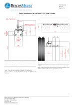
Typical Installation For Use With ‘J’ & ‘G’ Type Cylinder Typical panel weight is 15kg. Note - If option high pressure bank valves are used (see figure 1, item 19) the manifold width increases by 110mm per side. Note - ‘J’ type cylinders typically for Oxygen and Medical Air. ‘G’ type cylinders typically for Nitrous Oxide and N2O/O2 mix (Entonox). Atlas Copco Ltd. trading as Atlas Copco Medical Unit 18 Nuffield Way, Abingdon, Oxfordshire, UK OX14 1RL www.bea
カタログの3ページ目を開くBeaconMedaesのすべてのカタログと技術パンフレット
-
Series B Premium
3 ページ
-
Local alarm
4 ページ
-
Central alarm
4 ページ
-
Zone Valve Boxes
4 ページ
-
Ceiling Columns
2 ページ
-
Claw Medical Vacuum
8 ページ
-
Hose Assemblies
2 ページ
-
Biomaster Additive
4 ページ
-
Medical Gas Outlets
4 ページ
-
Lifeline Manifolds
4 ページ
-
Medical Air Dryers
2 ページ
-
Magnis MSV
2 ページ
-
mVAC
12 ページ
-
Lifeline® MCS
5 ページ
-
VAV05D-060H-D_V
4 ページ
-
VHV05D-060H-D_V
4 ページ
カタログアーカイブ
-
Claw Vacuum System
6 ページ


