
カタログの抜粋

Implants trauma Cannulated Tibia Nail
カタログの1ページ目を開く
1. introduction P. 5 Preface P. 6 Screw P. 6 Properties P. 7 Pre-operative measurement of nail Length P. 8 Indications & Contraindications 2. Surgical Technique P. 10 Pre-operative patient planning P. 10 Incision P. 11 Assembly of the insertion guide P. 12 Locating entry portal P. 12 Nailing P. 13 Proximal Locking P. 14 Measuring of proximal screw length P. 15 Distal Locking P. 16 Measuring of distal screw length P. 17 Removal of the insertion guide P. 17 Endcap insertion P. 19 Postoperative treatment P. 19 Nail removal 3. Information P. 21 Dotize® P. 22 Order list P. 26 Reconditioning Manual
カタログの3ページ目を開く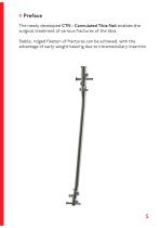
Preface The newly developed CTN - Cannulated Tibia Nail enables the surgical treatment of various fractures of the tibia. Stable, ridged fixation of fractures can be achieved, with the advantage of early weight bearing due to intramedullary insertion.
カタログの5ページ目を開く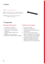
Spiral Drill, D=4.2mm, L=350mm, AO Connector Spiral Drill, Angledrived, D=4.2mm, L=140mm Shank, PRS, Solid, WS 3.5, L=230mm, AO Connector Properties Properties of the material: • Nail material: TiAl6V4 ELI • Material of screw: TiAl6V4 ELI • Easier removal of the implant if necessary • Improved fatigue strength of the implant • Reduced risk of cold welding • Reduced risk of inflammation and allergy • Anatomically shaped • Radiolucent insertion guide • Intramedullary insertion allows early weight bearing • Multi-direction proximal Locking • Dynamic interlock options to allow for fracture...
カタログの6ページ目を開く
1. Determine the nail length with the template (see right) and a X-Ray Pre-operative measurement of nail length Scale 1.6:1 2. Determine the nail length with the X-Ray ruler (59205). 3. Insert the calibrated D=3.0mm guide wire with ball tip (35301-800) or the D=2.5mm guide wire (35251-800) and read off the required nail length at the calibrated guide wire.
カタログの7ページ目を開く
Indications: ♦ Proximal, metaphyseal, diaphyseal and distal metaphyseal fractures ♦ Simple, segmental and comminuted fractures • Open fractures of the tibia ♦ Surgical correction of non-unions, mal-unions and delayed unions ♦ Pathological fractures ♦ Fractures involving osteopenic and osteoporotic bone Contraindications: ♦ Active infection near the fracture site ♦ Skeletally immature patients ♦ Severe osteoporosis or inadequate bone stock ♦ Skin and soft tissue problems ♦ Foreign body (material) sensitivity ♦ Obesity ♦ Lack of patient compliance
カタログの8ページ目を開く
Surgical Technique
カタログの9ページ目を開く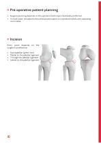
Pre-operative patient planning • Surgical planning depends on the operative technique individually preferred. • In most cases, the patient should be placed supine on a standard radiolucent operating room table. Incision Entry point depends surgeon‘s preference: • • • • Suprapatellar (green line) Medial to the patellar ligament Through the patellar ligament Lateral to the patell
カタログの10ページ目を開く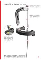
Assembly of the insertion guide fastening with the flatwrench, WS 20 (70020) fastening with the socket wrench, WS 10, L=250mm (561002-250) To attach the jig to the handle, rotate the spinning fastener clockwise. Turn it until it stops and move it into the provided slots (highlighted in yellow). Advice: To verify the correct assembly of the insertion guide, insert a tissue protection sleeve and a drill sleeve into a guide hole in the jig. Then push the drill through the drill sleeve in the appropriate nail interlock hole.
カタログの11ページ目を開く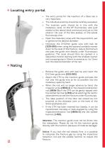
• The entry portal for the insertion of a tibiaL nail is very important. • The individual anatomy should be carefully evaluated. • The insertion point should be in line with the medullary canal on the AP fluoroscopy view (just medial to the lateral tibial eminence) and just on the anterior roll over of the tibia plateau on the lateral fluoroscopy view. • Open the medullary canal with the required drill, awl or gimlet to the desired diameter. • Introduce the D=3.0mm guide wire with ball tip (35301-800) when using the optional available reamer down to the level of the fracture, reduce the...
カタログの12ページ目を開く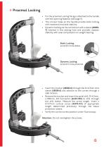
Proximal Locking • For the proximal Locking the jig is attached to the handle with the spinning fastener (see page 11). • The circular holes on the handle provide static locking with rotational and axial stability. • Dynamic locking can be carried out with a sleeve (1180087) inserted in the oblong hole and provides rotation stability with axial compression on weight bearing. Static Locking: eccentric hole distal Dynamic Locking: eccentric hole proximal • Insert the trochar (118008-8) through the D=4.3mm drill sleeve (118008-6) and advance to the cortex through a stab incision. • Remove the...
カタログの13ページ目を開く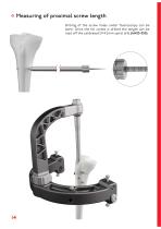
Measuring of proximal screw length Drilling of the screw holes under fluoroscopy can be done. Once the far cortex is drilled the length can be read off the calibrated D=4.2mm spiral drill (61423-350).
カタログの14ページ目を開く
Distal Locking • Distal locking is carried out using fluoroscopy and perfect circle technique. • Before locking, the correct reduction should be verified. • The spiral drill, angledrived, D=4.2mm, L=140mm, AO Connector (61427-140), is used to drill through the near and far cortex. • Measure the screw length. • Insert a D=4.7mm cortical screw (32475-XX) of appropriate length determined previously. • Verify the correct screw position under fluoroscopy. Attention: Do not overtighten the sc
カタログの15ページ目を開く
Measuring of distal screw length The distal screw length may also be determined using the standard depth gauge from the solid small fragment screws set (59022).
カタログの16ページ目を開く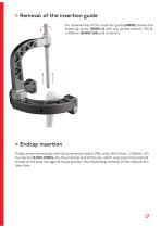
Removal of the insertion guide For disassembly of the insertion guide (118008) release the fastening screw (118008-4) with the socket wrench, WS 10, L=250mm (561002-250) and remove it. Endcap insertion Finally screw the endcap with the screwdriver shank, PRS, solid, WS 3.5mm, L=230mm, AO Connector (54353-230SH) into the proximal end of the nail, which will protect the internal thread of the tibia nail against tissue growth, thus facilitating removal of the implant at a later date.
カタログの17ページ目を開くI.T.S. のすべてのカタログと技術パンフレット
-
 ufs
ufs1 ページ
-
 DHL
DHL2 ページ
-
 ITS
ITS2 ページ
-
 PHL
PHL24 ページ
-
 ACLS
ACLS20 ページ
-
 CFN
CFN32 ページ
-
 OLS
OLS24 ページ
-
 PHLs
PHLs20 ページ
-
 SR Sacral Rods
20 ページ
-
 HCS
HCS24 ページ
-
 TOS Twist-Off Screw
20 ページ
-
 TLS
TLS20 ページ
-
 PRS-RX
32 ページ
-
 HLS
HLS20 ページ
-
 ES
ES20 ページ
-
 SR
SR20 ページ
-
 FL
FL24 ページ
-
 CAS
CAS40 ページ
-
 FCN
FCN20 ページ
-
 HOL
HOL24 ページ
-
 FLS
FLS24 ページ
-
 PFL
PFL20 ページ
-
 DTL
DTL24 ページ
-
 HTO
HTO24 ページ
-
 PTL
PTL32 ページ
-
 DFL
DFL32 ページ
-
 SCL
SCL32 ページ
-
 SLS
SLS24 ページ
-
 CAL
CAL20 ページ
-
 DUL
DUL24 ページ
-
 CLS
CLS28 ページ


