
カタログの抜粋

Implants trauma Proximal Lateral Tibia Locking Plate
カタログの1ページ目を開く
CAUTION: Federal Law (USA) restricts this device to sale by or on the order of a board certified physician. WARNING: If there is no sufficient bone healing, wrong or incomplete postoperative care, plate might break. All ITS plates are preformed anatomically as a matter of principle. If adjustment of the plate to the shape of the bone is required, this is possible by carefully bending gently in one direction once. Particular care is required when bending in the region of a plate hole, as deformation of the plate may lead to a failure of the locking mechanism. The plate must not be buckled or...
カタログの2ページ目を開く
1. Introduction P. 5 Preface P. 6 Screws P. 7 Properties P. 7 Preoperative identification of screw length P. 8 Indications & Contraindications P. 8 Time of operation 2. Surgical Technique P. 10 Pre-operative patient preparation P. 10 Assembling of the insertion guide/extraction instrument P. 11 Reduction P. 11 Access P. 12 Plate insertion P. 13 Temporary fixation with K-Wires P. 14 Reduction instrument P. 15 Intraoperative identification of screw length P. 16 Placement of the screws P. 17 Drilling optionally P. 20 Disassembling of the insertion guide P. 21 Postoperative treatment P. 21...
カタログの3ページ目を開く
Preface The newly developed LRS System - Locking Reconstruction System enables the medical treatment of fractures in the joint area with an optional less invasive method. The special feature of this implant is the free choice of screw placement. The user is able to set any desired screw in any hole. The system provides the opportunity to operate with or without a drill block in the joint area. Especially with complex fractures the free choice of screw angle (+/- 15°, see page 23) has advantages in the fracture treatment.
カタログの5ページ目を開く
Cancellous Screw, Locking, D=5.9mm Spiral Drill, D=3.5mm, L=280mm, AO Connector Screwdriver Shank, PRS, Solid, WS 3.5, L=230mm, AO Connector Spiral Drill, D=3.5mm, L=280mm, AO Connector Screwdriver Shank, PRS, Solid, WS 3.5, L=230mm, AO Connector Spiral Drill, D=3.2mm, L=280mm, AO Connector Screwdriver Shank, PRS, Solid, WS 3.5, L=230mm, AO Connector Cortical Screw, Locking, D=4.5mm Spiral Drill, D=3.2mm, L=280mm, AO Connector Screwdriver Shank, PRS, Solid, WS 3.5, L=230mm, AO Connector
カタログの6ページ目を開く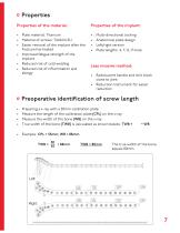
Properties Properties of the material: • Plate material: Titanium • Material of screws: TiAl6V4 ELI • Easier removal of the implant after the fracture has healed • Improved fatigue strength of the implant • Reduced risk of cold welding • Reduced risk of inflammation and allergy Multi-directional locking Anatomical plate design Left/right version Plate lengths: 4, 7, 12, 17-hole Less invasive method: • Radiolucent handle and drill block close to joint • Reduction instrument for easier reduction Preoperative identification of screw length • • • • Preparing a x-ray with a 50mm calibration...
カタログの7ページ目を開く
Indications, Contraindications & Time of operation Indications: For stabilization of fractures of the proximal tibia • Proximal shaft fractures • Metaphyseal fractures • Intra-articular fractures With advanced osteoporosis In cases of skin and soft tissue problems above the lateral epicondylus Obesity Lack of patient compliance Time of operation: • Primary: Within the first hours after trauma • Secondary: After swelling subsides, intermediate fixation with external fixation or extension
カタログの8ページ目を開く
Surgical Technique
カタログの9ページ目を開く
Pre-operative patient preparation • • • • Position the patient supine on a radiolucent table Leg freely movable X-rays of the lateral and anterior-posterior proximal tibia should be possible To flex the knee joint, a roll can be placed below the knee Assembling of the insertion guide 1 Assemble the insertion guide on the plate with the fixation screw (118002-7) Assembling of the clamping bolt with flat wrench, WS 11 (70011) Assembling of the reduction instrument
カタログの10ページ目を開く
Anatomic reposition of the fracture In intra-articular fractures reconstruct and stabilize the whole joint Possible temporary fixation with K-Wires Following x-ray control Straight, short, skin incision (see picture below) from Gerdy‘s tubercle 50mm to distal Open the space between the anterior tibial muscle and the periosteum Insert the plate between the periosteum and the muscle Anterolateral arthrotomy providing good control of the reduction
カタログの11ページ目を開く
Plate insertion • Insert the plate, assembled on the insertion guide, between the anterior tibial muscle and periosteum • Distal end of the plate should remain in constant contact with the bone • Position the proximal end of the plate against the lateral condyle (plate must lie flat up against the condyle. If it‘s problematic to find the correct position, enlarge the incision) • Verify the correct plate position under fluoroscopy and temporarily secure it with the tissue protection sleeve (118003-11), drill sleeve, D=1.7/3.6mm (118003-9/118003-10) and the inserted guide wire, steel,...
カタログの12ページ目を開く
Temporary fixation with K-Wires Fixation with K-Wires passed through tissue protection sleeves (118003-11) and inserted drill sleeve D=1.7/3.6mm (118003-9/118003-10) can be performed as soon as plate and bone have been optimally aligned. Distal fixation follows after proximal fixation. Insert trocar (57042) through the tissue protection sleeve (118003-11) in the most distal hole of the plate (guiding instrument) and advance to the plate after stab incision. Then, insert the retaining sleeve (118003-16), screw it onto the plate and place the D=1.6mm guide wire (35164-260) through the...
カタログの13ページ目を開く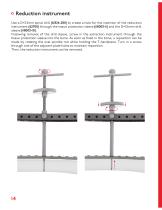
Reduction instrument Use a D=3.2mm spiral drill (61324-280) to create a hole for the insertion of the reduction instrument (62700) through the tissue protection sleeve (118003-11) and the D=3.6mm drill sleeve (118003-10). Following removal of the drill sleeve, screw in the extraction instrument through the tissue protection sleeve into the bone. As soon as fixed in the bone, a reposition can be made by rotating the oval spindle nut while holding the T-handpiece. Turn in a screw through one of the adjacent plate holes to maintain reposition. Then, the reduction instrument can be removed.
カタログの14ページ目を開くI.T.S. のすべてのカタログと技術パンフレット
-
 ufs
ufs1 ページ
-
 DHL
DHL2 ページ
-
 ITS
ITS2 ページ
-
 PHL
PHL24 ページ
-
 ACLS
ACLS20 ページ
-
 CFN
CFN32 ページ
-
 OLS
OLS24 ページ
-
 PHLs
PHLs20 ページ
-
 SR Sacral Rods
20 ページ
-
 HCS
HCS24 ページ
-
 TOS Twist-Off Screw
20 ページ
-
 TLS
TLS20 ページ
-
 PRS-RX
32 ページ
-
 HLS
HLS20 ページ
-
 ES
ES20 ページ
-
 SR
SR20 ページ
-
 FL
FL24 ページ
-
 CAS
CAS40 ページ
-
 FCN
FCN20 ページ
-
 HOL
HOL24 ページ
-
 FLS
FLS24 ページ
-
 PFL
PFL20 ページ
-
 DTL
DTL24 ページ
-
 HTO
HTO24 ページ
-
 DFL
DFL32 ページ
-
 SCL
SCL32 ページ
-
 SLS
SLS24 ページ
-
 CAL
CAL20 ページ
-
 DUL
DUL24 ページ
-
 CLS
CLS28 ページ


