- Company
- Products
- Catalogs
- News & Trends
- Exhibitions
activ L®

activ L®
- Product Features: The activ L® lumbar intervertebral disc prosthesis is designed to minimize over-distraction risks and is suitable for cases with low disc space. The spike version allows for intraoperative correction and offers primary stability similar to the keel version, with enhanced pull-out strength in the anterior-posterior direction.
- Safety Information: Do not combine components from different suppliers, and do not reuse previously implanted devices. Regular postoperative inspections are necessary to ensure proper functioning.
- Sterility: Implant components are provided sterile and should not be resterilized. They must remain in their original packaging until use.
- Size Estimation: Use CT-scan diagnostics and X-ray templates to assess the implant bed area and ensure proper vessel mobilization.
- Patient Positioning: Position the patient supine with slightly flexed hips for optimal imaging and access.
- Marking the Approach: Use lateral imaging to mark the incision, ensuring alignment with the intervertebral space.
- Skin Incision: A retroperitoneal approach is recommended to reduce complication risks.
- Anatomical Structures: Careful preparation of major vessels is crucial, with a vascular surgeon on call.
- Spike vs. Keel Version: The spike version is generally preferred due to its biomechanical advantages and reduced risk of vertebral endplate damage.
- S1 Design: The S1 plate option addresses specific anatomical needs, allowing for larger implant sizes.
- Midline Marking: Define the midline of the vertebral body under X-ray control.
- Discectomy and Segment Mobilization: Perform discectomy and cleanse endplates to facilitate osteointegration.
- Parallel Distraction, Height Measurement, and Size Verification: Use trial implants to verify size and ensure proper distraction under X-ray control.
Catalog excerpts

Aesculap Spine activ L® Lumbar Intervertebral Disc Prosthesis Operating technique
Open the catalog to page 1
Safety Information Product Features Patient Positioning Skin Incision Anatomical Structures Spike Version vs. Keel Version Size Estimation Instrumentation – Spike Version D.1.1 Discectomy and Segment Mobilization Parallel Distraction, Height Measurement and Size Verification Midline Marking Instrumentation – Keel Version D.2.1 Chisels for Keel Fixation Correction of Implant Position and Inlay Revision E.1 Correction of Implant Position Inlay Revision Implant Overview Instrument Overview
Open the catalog to page 3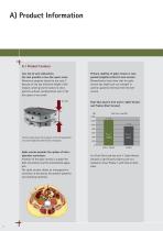
A.1 Product Features Less risk of over-distraction. Use also possible in low disc space cases: Numerous surgeons started to use activ L® because of the low minimum height of the implant, which gives the option to treat patients without overdistraction even if the disc space is very small. 8.5 mm Primary stability of spike version is comparable (slightly better) to keel version: Biomechanical tests show that the spike version has higher pull-out strength in anterior-posterior direction then the keel version. Push-Out-Load in N of activ L® Spike Version and Prodisc (Keel Version) (N) 1400 Clinical...
Open the catalog to page 4
A.2 Safety Information Under no circumstances may modular implant components from different suppliers be combined. Previously implanted devices may not be reused. Damage to the load-bearing structures of the implant may cause the loosening of components, their dislocation and migration, and other severe complications. Postoperatively, the implant should be inspected on a regular basis to determine whether it is functioning properly. A.3 Sterility The implant components are provided in protective packaging that is labeled to indicate its contents. The implant components are provided sterile. Implant...
Open the catalog to page 5
B.1 Size Estimation Assess the largest possible implant bed area using ct-scan diagnostics with x-ray templates and check the scale factor of the used template. Control the anatomy of the major vessels, especially the left common iliac vein. Is it possible to mobilize the vessels sufficiently and to move them away from your approach? Would a pararectus approach be easier? Warning: m There is a risk of selecting the wrong size of the prosthesis plate if an X-ray template with wrong scale is used. m Be sure to use an X-ray template of the correct scale. m Preoperative planning using X-ray templates...
Open the catalog to page 6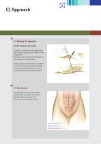
C.1 Marking the Approach Anterior Approach L4/L5, L5/S1 To mark the incision a lateral image is taken with a metal rod parallel to the defective disc compartment. The extension of this marking corresponds to the midpoint of the skin incision. The skin incision is marked under x-ray control so that the incision lies along the extended line of the intervertebral space. 5 – 8 cm is usually adequate for single level treatment. C.2 Skin Incision The approach should be retroperitoneal. Transperitoneal approaches carry a considerably higher complication risk (ileus, lesion of the presacral plexus)....
Open the catalog to page 7
C.3 Approach Midline Approach L5/S1 A midline approach is always used for the L5/S1 level. A midline approach or a pararectus approach (always left) are possible in the L3/4 and L4/5 segments. A Pfannenstiel´s incision or a linear midline incision are possible. Both sides are possible for the approach. If no other level is to be operated on, the right side may be preferred. Note: Advantages of the midline approach: m Considerably easier implant positioning, less retraction of the abdominal muscles required. Note: Advantages of the pararectus approach: m Simpler retroperitoneal preparation, less...
Open the catalog to page 8
C.4 Anatomical structures Midline + Pararectus Approach L5/S1 + L3/4, L4/5 Anterior transperitoneal Anterior retroperitoneal Antero-lateral retroperitoneal Antero-lateral transmucular
Open the catalog to page 9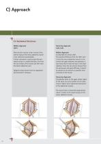
C.4 Anatomical Structures Midline Approach L5/S1 After the skin incision: linear incision of the anterior fascia of the rectus abdominis muscle a few millimeters paramedially. A blunt instrument is used to push the peritoneum away in a medial direction, first from the rear surface of the muscle and then from the lateral abdominal wall. Midline Approach: As described for ventral L5/S1. The essential difference from the L5/S1 level is that the rectus abdominis muscle in the central and upper abdomen also possesses a rear fascia which it does not have in the lower abdomen. Since this can only be...
Open the catalog to page 10
Pararectus Approach L3/4, L4/5 A blunt instrument is used to push the peritoneum away from the abdominal wall whilst monitoring the epigastric vessels. The ureter is prepared away from the operating site together with the peritoneum. The ventrolateral spine is exposed at the anterior margin of the psoas muscle. The neighbouring segment vessels are ligated and dissected, including the ascending lumbar vein for the approach to the L4/5 segment, so that the major vessels can be mobilized to the opposite side. The sympathetic nerve is mobilized in a lateral direction. If possible the situs is “fixed”...
Open the catalog to page 11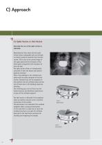
C.5 Spike Version vs. Keel Version Generally the use of the spike version is indicated. Biomechanical tests show that the spike version shows comparable pull-out strength in anterior-posterior direction then the keel version. This is due to the convex shape of the upper plate and the resistance of the three spikes compared to the resistance of only one keel. The spike version allows an intraoperative correction in both the lateral and anteriorposterior direction. There is less damage to the vertebral endplates with the spike compared to the keel version. Therefore less risk for migration of the...
Open the catalog to page 12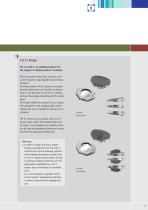
C.6 S1 Design The S1 plate is an additional option for the surgeon to address patient`s anatomy. There are patients who have a sacrum with a rather round or egg shaped cross-sectional footprint. For those patients the S1 plate has rounded posterior edges and can therefore be placed close to the posterior rim of the S1 vertebra without these edges protruding into the spinal canal. This might enable the surgeon to use a larger size compared to the standard plate, which reduces the risk of subsidence and nerve root irritation. S1 Plate spike version The S1 plate is just an option, there are of course...
Open the catalog to page 13All Aesculap® catalogs and technical brochures
 proGAV ® 2.0
36 Pages
 Targon® FN
36 Pages
 AESCULAP® NEUROENDOSCOPY
128 Pages
 AESCULAP® Metha®
28 Pages
 AESCULAP® BULLDOG CLIPS
8 Pages
 Quintex®
8 Pages
 MONOMAX®
16 Pages
 Premilene® Mesh Plug
8 Pages
 AESCULAP® Excia® 12/14
18 Pages
 Aesculap®
16 Pages
 VascuFlex®
12 Pages
 Aesculap Aeos®
16 Pages
 LC – LINEAR CUTTER STAPLER
6 Pages
 M.blue®
44 Pages
 Nelson® deluxe
8 Pages
 CARDIOLOGY
44 Pages
 Aesculap® Targon® RF
28 Pages
 Aesculap® OrthoPilot®
52 Pages
 TrendHip®
16 Pages
 proSA®
30 Pages
 AESCULAP® SINGLE USE PRODUCTS
88 Pages
 AESCULAP® CoreHip® SYSTEM
36 Pages
 AdTec® bipolar
8 Pages
 Aesculap Surgical Instruments
64 Pages
 EV3.0 CAMERA CONTROL UNIT
12 Pages


- Bone plate
- Compression plate
- Logistics trolley
- Metallic compression plate
- BBRAUN catheter
- Locking compression plate
- Surgery forceps
- Medical device trolley
- Grasping forceps
- Syringe
- Surgery electrode
- Human scissors
- Cannula
- Electrosurgical electrode
- Endoscope
- BBRAUN retractor
- Surgical system
- Container
- Orthopedic surgery instrument kit
- Reusable forceps