- Company
- Products
- Catalogs
- News & Trends
- Exhibitions
DCS Surgical Technique
1 /17Pages

DCS Surgical Technique
1 /17Pages
Catalog excerpts

Medical Implants Medical Implants Surgical Technique
Open the catalog to page 1
Medical Implants Astrolabe recognizes that proper surgical procedures and techniques are responsibilities of medical professionals. The following guidelines are provided for information purposes only. Each surgeon must evaluate the appropriateness of the procedures based on their medical training, experience and condition of the patient. Before using the system, the surgeon must consult the operating instructions for additional warnings, precautions, indications, contraindications and adverse effects. NOTE: Large Fragments Instruments are complementary to this System. Surgical Technique - DHS-DCS...
Open the catalog to page 2
Large Fragments Surgical Technique - DHS-DCS
Open the catalog to page 3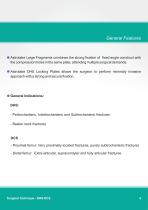
• Astrolabe Large Fragments combines the strong fixation of fixed angle construct with the compression holes in the same plate, attending multiple surgical demands. • Astrolabe DHS Locking Plates allows the surgeon to perform minimaly invasive approach with a strong and secure fixation. - Pertrochanteric, Intertrochanteric and Subtrochanteric fractures - Basilar neck fractures - Proximal femur: Very proximally located fractures, purely subtrochanteric fractures - Distal femur: Extra-articular, supracondylar and fully articular fractures Surgical Technique - DHS-DCS
Open the catalog to page 4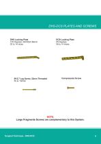
DHS-DCS PLATES AND SCREWS DHS Locking Plate 135 Degrees, Std/Short Barrel 02 to 14 Holes DCS Locking Plate 95 Degrees 06 to 14 Holes Compression Screw NOTE: Large Fragments Screws are complementary to this System. Surgical Technique - DHS-DCS
Open the catalog to page 5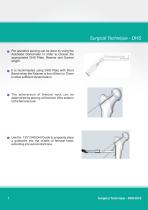
Surgical Technique - DHS Pre operative planing can be done by using the Astrolabe Goniometer in order to choose the appropriated DHS Plate, Reamer and Screws length. It is recommeded using DHS Plate with Short Barrel when the Reamer is from 65mm to 75mm to allow sufficient dynamization. The anteversion of femoral neck can be determined by placing a Kirschner Wire anterior to the femoral neck. Use the 135° DHS Drill Guide to propperly place a guidewire into the middle of femoral head, extending into subcondral bone. Surgical Technique - DHS-DCS
Open the catalog to page 6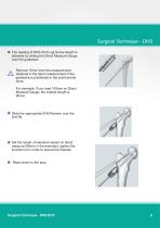
Surgical Technique - DHS The reading of DHS-DCS Lag Screw length is obtained by sliding the Direct Measure Gauge over the guidewire. Remove 10mm from the measurement obtained in the direct measurement if the guidewire is positioned in the subchondral bone. For exemple: If you read 100mm on Direct Measure Gauge, the implant length is 90mm. Slide the appropriate DHS Reamer over the Drill Bit Set the length of selected implant on direct measure (90mm in the exemple), tighten the knurled nut in order to secure the Reamer .Ream down to the stop. Surgical Technique - DHS-DCS
Open the catalog to page 7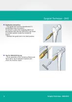
- The guide wire must be repositioned if it accidentally loses its position. To reinsert it, place the Centering Sleeve on the reamed hole with the DHS-DCS Lag Screw in inverted position inside the Centering Sleeve. - Reinsert the guide wire in its initial position. - Once assembly of the Centering Sleeve and Tap is done, tap to selected measure and check the insertion depth. Surgical Technique - DHS-DCS
Open the catalog to page 8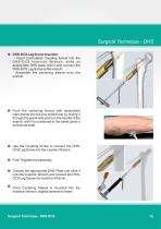
Surgical Technique - DHS DHS-DCS Lag Screw Insertion - Insert Cannulated Coupling Screw into the D H S - D C S I n s e r t i o n Wr e n c h , s l i d e a n appropriate DHS plate onto it and connect the DHS-DCS Lag Screw to the wrench. - Assemble the centering sleeve onto the wrench. Push the centering sleeve with assembled instruments into the pre-drilled hole by sliding it through the guide wire and turn the handle of the wrench until it is positioned in the same plane o as femoral shaft. Use the Coupling Screw to connect the DHSDCS Lag Screw into the insertion Wrench Fully Thighten the assembly....
Open the catalog to page 9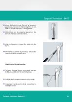
• Once DHS-DCS Lag Screw is properly positioned, remove the Centering Sleeve and slide DCS Plate over DHS-DCS Lag Screw. • DHS Plate can be properly aligned on the femoral shaft due to its free rotation. • Use the Impactor to impact the plate onto the bone. • Once DHS-DCS Plate is positioned, remove the Insertion Wrench and guide wire. • To insert Cortical Screws in the shaft, use the Drill Guide and the Drill Bit to drill the holes. • Use the Depth Gauge to measure screw length • Use proper Handle and the Shaft Screwdriver to insert the screws.
Open the catalog to page 10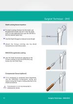
• To insert Locking Screws into the shaft, use threaded Drill Guide and turn it into the plate until it is fully tightened then use the Drill Bit to drill the desired plate hole. • Use the Depth Gauge to measure screw length • Attach the Torque Limiting into the Shaft Screwdriver to insert the screws. # Use the Shaft Screwdriver attached to the Torque Limiting to lock the DHS-DCS Lag Screw into the DHS Plate. # If it is necessary to compress bone fragments, use the DHS-DCS Compression Screw and insert it using the Torque Limiting attached to the Shaft Screwdriver. A Compression is not recommended...
Open the catalog to page 11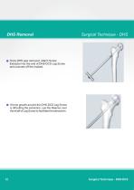
Once DHS was removed, attach Screw Extractor into the end of DHS-DCS Lag Screw and unscrew off the implant. If bone growth around the DHS-DCS Lag Screw is dificulting the extraction, use the Reamer over the shaft of Lag Screw to facilitate the extractioin. Surgical Technique - DHS-DC
Open the catalog to page 12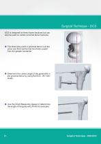
Surgical Technique - DCS DCS is designed for femur lower fractures but can also be used on certain proximal femur fractures. The ideal entry point in proximal femur is at the union one third ventral and two thirds caudal from the greater trochanter Determine the correct angle of the guide wire in the proximal femur by using the DCS - 95° Drill Guide. Use the Direct Measuring Gauge to determinne the length of the guide wire (70mm for exemple) Surgical Technique - DHS-DCS
Open the catalog to page 13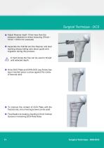
• Adjust Reamer depth 10mm less than the measure obtained on direct mesuring (70mm -10mm = 60mm for exemple) • Assemble the Drill Bit and the Reamer and start reaming always taking care about guide wire migration during this process. A In hard bones the Tap can be used to thread until selected depth. # Once DCS Plate and DHS-DCS Lag Screw has been inserted place a screw against the cortex of femoral neck • To improve the contact of DCS Plate with the fracture site, one or two lag screws can be used # Final fixation is made by inserting 4.5mm Cortical Screws in remaining DCs Plate holes. Surgical...
Open the catalog to page 14All Astrolabe catalogs and technical brochures
 Box Components SMA 2,7
8 Pages
 Box Components DRP 2,7
8 Pages
 Box Components RSS 2,7
8 Pages
 Box Components Small Fragments
28 Pages
 Box Components Cannulated 7,0mm
12 Pages
 Box Components Lapidus 2,7
10 Pages
 Arrow Plate 3,5
10 Pages
 Midfoot 2,7
10 Pages
 Rearfoot 3,5
16 Pages
 Metaphyseal 3,5 / 4,5
8 Pages
 Malleolus 3,5mm
8 Pages
 Box Components RCS 2.0/2.7
12 Pages
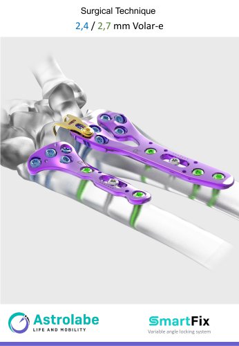 Volar -E Surgical Technique
33 Pages
 Box Components ForeFoot
12 Pages
 Box Components Fíbula
12 Pages
 Box Components RLS
8 Pages
 Box Components Akin & Weil
8 Pages
 Box Components Hallux Valgus
10 Pages
 Box Components CMS
10 Pages
 Catalog 4Hand
32 Pages
 DCS Box Components
10 Pages
 Surgical Technique DCS
17 Pages
 Box Components DCS
10 Pages
 Box Components Tibia Osteotomy
12 Pages
 Box Components Large Fragments
28 Pages
 Box Components Large Fragments
28 Pages
 Box Components Cannulated Screws
10 Pages
 Box Components Clavicle
10 Pages
 Box Components Volar-E
16 Pages
 Box Components Mallelous 3.5
8 Pages
 Reamers Astrolabe
12 Pages
 OTHOS System - Tibia Osteotomy
16 Pages
 VolarE System - Distal Radius
11 Pages
 2.7/3.5 Hallux Valgus System
20 Pages


- Bone plate
- Compression plate
- Metallic compression plate
- Locking compression plate
- Titanium compression plate
- Distal compression plate
- Compression bone screw
- Metallic compression bone screw
- Proximal compression plate
- Forearm compression plate
- Lateral compression plate
- Medial compression plate
- Metal burr
- General purpose compression bone screw
- Tibia compression plate
- Humerus compression plate
- Cannulated compression bone screw
- Radius compression plate
- Arthrodesis plate
- Metallic arthrodesis plate