- Catalogs
- BeaconMedaes
- Emergency Reserve Manifold HTM/ISO Specification Sheet
Emergency Reserve Manifold HTM/ISO Specification Sheet
1 /5Pages

Emergency Reserve Manifold HTM/ISO Specification Sheet
1 /5Pages
Catalog excerpts
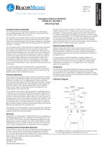
Emergency Reserve Manifold HTM02-01/ ISO7396-1 SPECIFICATION Emergency Reserve Manifold The Emergency Reserve Manifold shall conform to NHS Health Technical Memorandum No. 02-01 (HTM 02-01), BS EN ISO 7396-1, BS EN ISO 15001 and BS EN ISO 10524-2. The manifold control system shall provide an uninterrupted supply of a specific medical gas from equally sized high pressure cylinder banks via a suitable arrangement of pressure regulators, providing a constant nominal downstream pipeline gauge pressure of 400 kPa, 700 kPa or 1,100 kPa. The Emergency Reserve Manifold shall be supplied fully assembled and tested. A Gem Shield terminal unit test point shall be fitted, which shall be isolated from the main supply with a ball valve. The manifold shall be supplied with a non-return valve and lockable line isolation valve for connection to the distribution system, enabling a continuous supply of gas to the distribution system upon failure of the normal supply. High pressure bank isolation valves shall be supplied to enable one bank to be designated as “duty” (open in normal operation) and one bank to be designated as “standby” (closed in normal operation). Visual indication of the open bank shall be included. To simplify installation the manifold shall be supplied with the primary manifold headers and non-return valves for connection of tailpipes. The complete manifold shall be fitted to a wall mounting plate attached to the wall with four screws. Pressure Regulation There shall be two separate stages of pressure regulation to enable high peak flow rates without a significant reduction in downstream pressure. The inlet of the 1st stage regulator shall be protected from the particulate matter by a 25µm sintered brass filter. Sintered aluminium bronzes shall not be used. Regulators shall comply with BS EN ISO 10524-2 and shall be supplied with documented test reports upon request, confirming successful completion of the oxygen ignition tests stated therein. EMERGENCY RESERVE MANIFOLD pressure in the “Duty” bank falls to 68 bar (14 bar for nitrous oxide), a “Reserve Low” or “Reserve Fault” alarm condition shall be initiated by a contact pressure gauge, which shall be indicated on the relevant medical gas central alarm panel and/or primary supply automatic manifold panel. The “Standby” bank shall also be provided with a contact pressure gauge, such that any leakage of gas over an extended period of which causes the pressure in the standby bank to fall below 68 bar (14 bar for nitrous oxide), will also initiate a “Reserve Low” or “Reserve Fault” alarm condition. Modular Header Manifolds Modular Header Manifolds shall provide connection points for flexible cupronickel tailpipes. Pin indexed tailpipes shall comply to EN ISO 407:2004 as required. Non-return valves shall be fitted to each tailpipe connection point to protect the system in the event of a tailpipe fracture. Corner connectors shall be available to enable installation of manifold headers around corners of the manifold room. A custom length corner connector shall also be available to enable header manifolds to be installed in a ‘U’ configuration across 3 adjacent walls of a manifold room. CE Marking The standard range of BeaconMedæs Emergency Reserve Manifolds are ‘CE’ marked under the Medical Devices Directive 93/42/EEC with approval from notified body no. 0088 (Lloyd’s Register Quality Assurance). Under this directive, the specified products are classified as Class IIb Medical Devices. Schematic Diagram The manifold control system shall be capable of supplying a flow of 1,200 l/min to a nominal 400 kPa distribution system, 2,000 l/min to a nominal 700 kPa distribution system and a flow of 2,000 l/min to a nominal 1,100 kPa distribution system based on a 10% reduction in flowing pressure from a static pressure set point. All regulators shall be protected from over-pressurisation by relief valves, which shall be pre-piped into the manifold exhaust line stub pipe to enable the gas to be taken away and vented to atmosphere safely. Relief valves shall not be vented into the manifold room. Alternatively, for small installation (required flow less than 200 l/min) a simplified version of Emergency Reserve Manifold with multistage regulator (ERM ECO) shall be available. Materials All polymers and elastomers in the gas flow that can be subjected to working pressure greater than 3,000 kPa shall be halogen-free. The use of PTFE, PCTFE, Viton and other halogenated polymers in these applications is strictly prohibited. Non-return valves fitted to header manifolds shall have a metallic seat with ceramic ball. Soft seat nonreturn valves utilising polymers or elastomers are not acceptable. Emergency Reserve Manifold Operation Either the left or right hand of the manifold bank shall be designated as “Duty”, with the other manifold bank designated as “Standby” by use of the high pressure bank isolation valves. When the bank Atlas Copco Ltd. trading as Atlas Copco Medical Unit 18 Nuffield Way, Abingdon, Oxfordshire, UK OX14 1RL www.beaconmedaes.com Note: ERM ECO based on a multistage pressure regulator, where 1s
Open the catalog to page 1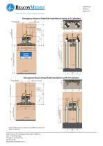
Emergency Reserve Manifold Installation with J or G Cylinders Emergency Reserve Manifold Installation with VF Cylinders 022mm Pipeline Note: Dimensions for standard and ERM ECO version of ERM are identical. Atlas Copco Ltd. trading as Atlas Copco Medical Unit 18 Nuffield Way, Abingdon, Oxfordshire, UK OX14 1RL www.beaconmedaes.com
Open the catalog to page 2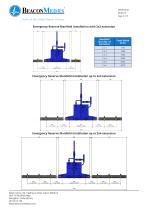
Emergency Reserve Manifold Installation with 2x2 extension Manifold Size (No. of Cylinders) Emergency Reserve Manifold Installation up to 2x3 extension Emergency Reserve Manifold Installation up to 2x4 extension
Open the catalog to page 3
Emergency Reserve Manifold Installation up to 2x5 extension Emergency Reserve Manifold Installation up to 2x6 extension Atlas Copco Ltd. trading as Atlas Copco Medical Unit 18 Nuffield Way, Abingdon, Oxfordshire, UK OX14 1RL www.beaconmedaes.com
Open the catalog to page 4All BeaconMedaes catalogs and technical brochures
 Series B Premium
3 Pages
 Central alarm
4 Pages
 Digital Medical Gas Alarms
4 Pages
 Zone Valve Boxes
4 Pages
 mVAC Medical Vacuum Systems
8 Pages
 Medical Scroll Air Retrofit
4 Pages
 Ceiling Columns
2 Pages
 Medical Vacuum Filters
4 Pages
 Claw Medical Vacuum
8 Pages
 Biomaster Additive
4 Pages
 Medical Gas Outlets
4 Pages
 Lifeline Manifolds
4 Pages
 Medical Equipment Air
8 Pages
 ZMED Medical Air Systems
6 Pages
 Scroll Medical Air Systems
8 Pages
 Medical Air Dryers
2 Pages
 Magnis MSV
2 Pages
 mVAC
mVAC12 Pages
 Lifeline® MCS
5 Pages
 VHV05D-060H-D_V
4 Pages


Archived catalogs
 Local alarm
4 Pages
 Medical Instrument Air
4 Pages
 VAV05D-060H-D_V
4 Pages
 Medical Gas Retrofit Alarm
2 Pages
 Hose Assemblies
2 Pages
 Medical Gas Outlets_2009
4 Pages
 Medical Gas Alarm Systems
4 Pages
 Oxygen and Air Flowmeters
2 Pages
 Suction & Oxygen Therapy
2 Pages
 Medical Air Desiccant Dryers
2 Pages
 Instrument Air White Paper
39 Pages
 Z MED Medical Air Systems
6 Pages
 Claw Vacuum System
6 Pages


- Dry air compressor
- Hospital compressor
- Gas outlet
- Ceiling-mounted medical supply system
- Intensive care medical supply system
- Gas valve
- Laboratory air sterilizer
- Silent compressor
- Compact air sterilizer
- Medical gas manifold
- Vacuum system
- Medical gas valve
- Medical monitoring system
- Supply column
- Anesthetic gas alert system
- Medical vacuum system
- DIN outlet
- Plug-in type vacuum regulator