- Catalogs
- BeaconMedaes
- Medipoint 26 Local Alarm HTM/ISO Specification Sheet
Medipoint 26 Local Alarm HTM/ISO Specification Sheet
1 /3Pages

Medipoint 26 Local Alarm HTM/ISO Specification Sheet
1 /3Pages
Catalog excerpts

© Medipoint 26 Local Alarm Medical Gas Area Alarm SPECIFICATION BeaconMed/es Part of the Atlas Copco Group MEDIPOINT 26 AREA ALARM Medical Gas Area Alarm Each medical gas area alarm panel shall be capable of monitoring 6 medical gas services by means of pressure sensors, which detect deviations from the normal operating limits of either pressure or medical vacuum. The medical gas area alarm shall fully comply with the requirements of HTM2022, HTM 02-01, C11, BS EN 60601-1 and BS EN 60601-1-2 and BS EN ISO 7396-1 The cover, backbox and bezel (if required) shall be polyester powder coated in a RAL9010 30% gloss finish. A single tamperproof fastener shall be used to gain access to the hinged door. The hinge shall operate through a minimum of 1200 to provide adequate access. Antimicrobial Additive User accessible parts such as the back box, bezel and alarm fascia cover shall include a silver antimicrobial additive for inherent antimicrobial protection. System Operation Each gas service shall be displayed by coloured LED's to show 'Normal' (green), 'Low' and 'High Pressure' (red) conditions. Medical vacuum systems shall be displayed in the 'Normal' (green) and 'Low Vacuum' (red) conditions only. Failure indicators shall be displayed by flashing lights and normal indications shall be steady. Each LED block indicator shall be a plug-in component with individual long life LED's connected in parallel in two banks to provide duplex circuits. An audible warning shall sound simultaneously with any failure indication and a mute facility shall be provided. Following a mute selection the audible will resound after approximately 15 minutes, or shall operate simultaneously should a further alarm condition occur. A "Mute" switch shall be provided inside the panel for use during any maintenance resulting in prolonged pipeline or plant shutdown. This facility shall automatically reset when the gas service returns to normal. The alarm panel shall have a 'Test' facility to prove the integrity of the internal circuits, LED's and audible warning. The alarm panel shall incorporate a volt free normally closed relay to allow for interconnection to either a medical gas central alarm system or an event recording circuit of a building management system. Each alarm shall provide a green LED to indicate that electrical power is available at the panel and a red LED to indicate 'System Alarm'. In the event of an electrical power supply failure the 'System Alarm' LED shall illuminate (flashing) and the audible warning shall be delayed for 30 seconds to enable standby generator tests. Line contact monitoring circuits shall be provided to constantly monitor the integrity of the input sensors and interconnecting wiring. In the event of any fault the line contact monitoring circuits shall initiate the specific gas service failure indication, a 'System Alarm' indication and an audible warning. Further aids to fault diagnosis shall be provided by means of varying flashing rates whilst operating the 'Test' switch. A simple data connection shall be provided to allow connection of up to 5 repeater panels, enabling the visual and audible alarm signals to be repeated at other locations within a department. Pressure and Vacuum Switches Pressure and vacuum switches shall be manufactured with brass wetted parts and house a PCB with line contact monitoring resistors. Electrical connectors shall be designed for frequent disassembly. Spade connectors are not acceptable. Pressure switches shall include both high and low pressure settings in the same switch, using only a single %" BSPP threaded pipeline connection to minimise the number of sealed joints. The body and housing of the pressure switch shall be manufactured from impact resistance, rigid and inherently corrosion proof materials. Elastomers and plated or coated mild steel are not acceptable materials. Pressure switches shall connect directly to the area alarm panel. It is not acceptable to install a separate connection box to convert switch signals to a data signal. Atlas Copco Ltd. trading as Atlas Copco Medical Unit 18 Nuffield Way, Abingdon, Oxfordshire, UK OX14 1RL www.beaconmedaes.com
Open the catalog to page 1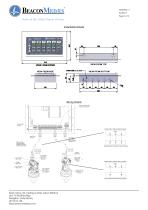
Installation Details Remote audible terminals C H L C H L C H L C H L C H L C H L A B A B S Power supply printed circuit board located with back box Data connection to repeat display to another panel Relay no-volt terminals Wiring example: 6 gas alarm panel (oxygen and vacuum shown only for clarity) Remote audible terminals Earth stud Power supply printed circuit board located with back box Wiring Detailsno-volt Relay terminals Mains electrical power supply Live(L), Neutral(N) and Earth( ) Data connection to repeat display to another panel Wiring example: 6 gas alarm panel (oxygen and vacuum...
Open the catalog to page 2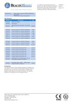
In an effort to continuously improve our products, the right is reserved to change the specification of the items described herein at any time. Please contact us for further information and up to date specifications. Power failure to panel SYSTEM ALARM (flashing) Audible 'POWER ON' indicator extinguished Screened Alarm Cable - MP26 alarm pressure switch connection CE Marking The standard range of BeaconMedss Medipoint 26 Medical Gas Area Alarms are 'CE' marked under the Medical Devices Directive 93/42/EEC with approval from notified body no. 0088 (Lloyd's Register Quality Assurance). Under this...
Open the catalog to page 3All BeaconMedaes catalogs and technical brochures
 Series B Premium
3 Pages
 Central alarm
4 Pages
 Digital Medical Gas Alarms
4 Pages
 Zone Valve Boxes
4 Pages
 mVAC Medical Vacuum Systems
8 Pages
 Medical Scroll Air Retrofit
4 Pages
 Ceiling Columns
2 Pages
 Medical Vacuum Filters
4 Pages
 Claw Medical Vacuum
8 Pages
 Biomaster Additive
4 Pages
 Medical Gas Outlets
4 Pages
 Lifeline Manifolds
4 Pages
 Medical Equipment Air
8 Pages
 ZMED Medical Air Systems
6 Pages
 Scroll Medical Air Systems
8 Pages
 Medical Air Dryers
2 Pages
 Magnis MSV
2 Pages
 mVAC
mVAC12 Pages
 Lifeline® MCS
5 Pages
 VHV05D-060H-D_V
4 Pages


Archived catalogs
 Local alarm
4 Pages
 Medical Instrument Air
4 Pages
 VAV05D-060H-D_V
4 Pages
 Medical Gas Retrofit Alarm
2 Pages
 Hose Assemblies
2 Pages
 Medical Gas Outlets_2009
4 Pages
 Medical Gas Alarm Systems
4 Pages
 Oxygen and Air Flowmeters
2 Pages
 Suction & Oxygen Therapy
2 Pages
 Medical Air Desiccant Dryers
2 Pages
 Instrument Air White Paper
39 Pages
 Z MED Medical Air Systems
6 Pages
 Claw Vacuum System
6 Pages


- Valve
- Dry air compressor
- Hospital compressor
- Gas outlet
- Ceiling-mounted medical supply system
- Intensive care medical supply system
- Gas valve
- Laboratory air sterilizer
- Silent compressor
- Manifold
- Compact air sterilizer
- Medical gas manifold
- Medical gas valve
- Medical monitoring system
- Supply column
- Medical vacuum system
- DIN outlet
- Anesthetic gas alert system
- Plug-in type vacuum regulator