Surgical procedure Total knee joint replacement type SVS

Surgical procedure Total knee joint replacement type SVS
This document provides a comprehensive guide on the surgical procedure for total knee joint replacement using the BEZNOSKA knee joint replacement design. It focuses on minimal bone resection, optimal joint surface shape, and functional stability with minimal polyethylene wear.
Size Range
The implants are available in various sizes to fit different anatomical needs. The tibial component is made from Ti6Al4V alloy and comes in six sizes, while the femoral component is made from CoCrMo alloy. The PE insert is available in five thicknesses.
Instrumentarium
The instrumentarium is modular and extensive, designed for precise implant fixation. It includes separate cassettes for femoral, tibial, and common instruments, facilitating the preparation and adjustment of anchoring surfaces.
Surgical Technique
The surgical procedure is modular, allowing flexibility in the order of steps. It includes femoral and tibial resections, with specific steps for each, such as opening the bone marrow femoral canal and adjusting the tibial component rotation.
Femoral Resection
The procedure involves opening the bone marrow femoral canal, centering the femur, adjusting the resection level, and performing distal femoral resection using a template-guided saw.
Tibial Resection
This involves preparing the tibial surface, performing the resection, and adjusting the rotation of the tibial component, followed by a trial reduction before final implantation.
Femoral Positioning and Resection Procedures
The document details femoral positioning and resection, including the use of templates for ventral, dorsal, and oblique resections, and enlarging the intercondylic space.
Tibial Resection Preparation
The tibial targeting device is used to align with the tibial plateau and ankle center, with adjustments made using corrective resection blocks.
Adjustment of Tibial Component Rotation
A tibial centration template is used to adjust the rotation, secured with fixation nails.
Preparation of the Hole for Tibial Component Stem
A drilling sleeve is used to prepare the canal for the stem, followed by a punch to complete the preparation.
Implantation Procedure
Bone cement is used to fix the components, starting with the tibial plateau followed by the femoral component. Proper cement application is crucial for stability.
Implant Set Requirements
The implant set includes a stabilized femoral component, tibial component with a stem plug, stabilized PE insert, and a connecting screw.
Completion of Surgery
The surgery concludes with the reconstruction of the extension apparatus, wound closure, and application of a cover dressing.
Contact Information
For further information, contact BEZNOSKA, s.r.o., Dělnická 2727, 272 01 Kladno, Czech Republic.
Catalog excerpts

Surgical procedure Total knee joint replacement type SVS Primary Implants – Knee
Open the catalog to page 1
Surgical Technique Basic information about implants and instruments Surgical Technique Femoral resection Step I – Opening of bone marrow femoral canal Step II – Centration of femur Step IV – Distal femoral resection Step V – Determination of the size of femoral component Step VI – Ventral and dorsal femoral resection Step XII – Preparation of the hole for tibial component stem Step VIII – Intercondylic femoral resection Tibial resection Step XI – Adjustment of tibial component rotation Step XII – Preparation of the hole for tibial component stem Step IX – Preparation of tibial resection Step...
Open the catalog to page 2
Surgical Technique The BEZNOSKA knee joint replacement design replaces the posterior cruciate ligament and was constructed based on current state-of-the-art technology, mainly based on our own experience with the standard BEZNOSKA/S.V.L. cemented total joint replacement. It enables the simple and precise fixation of the implant during a minimal bone resection. Optimization of the shape of joint surfaces enables a maximal range of motion with good functional stability and minimal risk of polyethylene wear (PE). The range of supplied sizes, always in the right and left form for each, provides complete coverage...
Open the catalog to page 3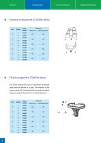
Introduction Instrumentarium Surgical Technique ■ Femoral component (CoCrMo alloy) ■ Tibial component (Ti6Al4V alloy) The tibial component uses an asymmetrical design (right and left forms) in 6 sizes. The implant is the same as type SVL (standard) with the option to either retain or replace the posterior cruciate ligament.
Open the catalog to page 4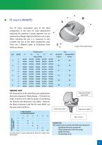
■ PE insert (UHMWPE) The PE insert (articulation part of the tibial component) in the form for total replacement replacing the posterior cruciate ligament has an asymmetrical design (right and left forms) in 6 sizes. When selecting the size, it is necessary to also consider the size of the tibial component used. There are 5 different types of thicknesses from which to choose. The table above is always applicable for both the R (right) and L (left) designs. Implant set The implant must contain the following elements: - Stabilized femoral component - Tibial component with stem plug - Connecting...
Open the catalog to page 5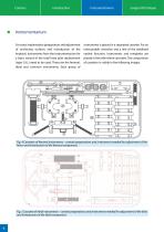
Surgical Technique Instrumentarium For exact implantation (preparation and adjustment of anchoring surfaces and introduction of the implant), instruments from the instrumentarium for a basic variant of the total knee joint replacement (type S.V.L) need to be used. These are the femoral, tibial and common instruments. Each group of instruments is placed in a separated cassette. For an intercondylic resection and a test of the stabilized variant function, instruments and templates are placed in the other three cassettes. The composition of cassettes is visible in the following images. Fig. 4 Cassettes...
Open the catalog to page 6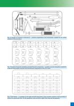
Fig. 6 Cassette of common instruments – contains preparations and instruments needed for the whole duration of the procedure. Fig. 7 Cassette of resection templates and trial femoral components – contains resection templates needed for a precise intercondylic resection and trial femoral components in the S.V.S. form. Fig. 8 Trial inserts – 2 cassettes (in the right and left knee forms). Every cassette contains a full assembly of inserts for a particular form. For the operation, only one (left or right) form may ever be prepared.
Open the catalog to page 7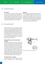
Approach The instrumentarium enables this joint replacement to be comfortably implanted through any of the standard surgical approaches used during the replacement of a knee joint. It does not require any changes in the surgical methods used in a particular site. The procedure is not influenced by the use of a tourniquet to achieve a bloodless field. Femoral Resection After reaching the knee joint, ensuring the standard release of soft tissues, and positioning the knee joint to flexion, it is suggested, but not required, to remove all osteophytes along the edges. This enables a more exact determination...
Open the catalog to page 8
connecting sleeve 4 is introduced (without force) into the prepared hole (see Figure 9). This sleeve is constructed with an inclination to a valgus position at 5°, 7° or 9°. The surgeon ensures that the appropriate lateral marking of the sleeve (R or L) is pointing upwards and is visible to the surgeon (see Figure 10). Turning of the assembly on the centration nail is used to set the correct rotation, to punch on the tips of the frontal surface of the centration device (at least to one of the condyles), and to secure it into the selected position (rotation). In this phase, the correct setting...
Open the catalog to page 9
III. Resection level adjustment on the distal end of femur - Procedure On the upper cylindrical measure gauge of the correctly introduced femoral centration device which is fixed with at least one pin, a template for distal resection 7 (see Figure 12) is to be set up. By moving along the scale (4 to 20 mm in extent) the optimal level of resection (from the construction of the femoral component, it is usually 8 or 10 mm) is set (see Figure 13). Now, we pre-drill the holes with a drill of 3.2 mm 8 from the set of common instruments (holes are marked with „O“), and two fixation nails are introduced...
Open the catalog to page 10
IV. Distal femoral resection - Procedure The resection is performed with a precise cut using a saw leaf along the distal surface of the resection template (see Figure 17a). Pressure must be kept on the saw leaf, so that there is maximal contact between the saw leaf and the template surface. The resection template may be supplemented with a guiding bar 10 from the cassette of universal instruments, placed in the holes on the edge of the resection template 7 (Figure 17b). The space between the guiding bar and the resection surface of the template corresponds to the thickness of the saw leaf. This...
Open the catalog to page 11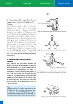
V. Determination of the size of the femoral component and the creation of guiding holes Procedure According to the assumed size of the femoral component, we choose one of two femoral positioning templates 11 (large or small). The template chosen is placed on the distal resection surface of the femur, so that the lower flanges of the template are inserted behind the dorsal part of the condyles and the apex of the rotating arm is touching the ventral cortical bone of the femur (see Figures 19a, 19b). The position of the symmetrically placed template is fixed by tightening the two tips. By viewing...
Open the catalog to page 12All Beznoska catalogs and technical brochures
 SKIN STAPLER 35W
1 Page
 Cementless cup – type SF
20 Pages
 Radial Head Replacement
12 Pages
 Humeral head resurfacing
12 Pages
 Hip Joint Head Replacements
8 Pages
 Cemented femoral stem - type CSC
16 Pages
 Hip Hemiarthroplasty – type CSB
20 Pages
 Cerclage System
12 Pages
 Implants for Traumatology
16 Pages
 Revision systems
32 Pages
 Implants for primary surgery
44 Pages
 Individual oncological implants
24 Pages


- Femoral stem
- Knee prosthesis
- Acetabular prosthesis
- Cementless femoral stem
- Cementless acetabular prosthesis
- Cemented femoral stem
- Femoral head prosthesis
- Fixed-bearing knee prosthesis
- Revision femoral stem
- Revision knee prosthesis
- Cemented knee prosthesis
- Cemented acetabular prosthesis
- Revision acetabular prosthesis
- Digit joint implant
- Tibial bearing
- Trapeziometacarpal joint implant