

Total Knee Joint Replacement Type CMS

Total Knee Joint Replacement Type CMS
The BEZNOSKA/CMS knee joint replacement implant is designed from clinical experience with oncological knee replacements. It offers simple fixation with intramedullary stems and can be combined with partial femur and tibia replacements, ensuring maximal mobility and stability with minimal polyethylene wear.
The implant is available in various sizes with symmetrical tibial components and left/right femoral components. It includes polyethylene liners of different thicknesses and stems of varying diameters and lengths to suit different implantation scenarios.
The instrumentation set is designed for precise centering and fitting of the implant, involving defined steps using resection blocks along the intramedullary bar. Proper instrument handling and adherence to specific procedures are crucial.
The surgical procedure includes opening and grinding the bone marrow canal, inserting a centering rod, preparing the tibial resection, and setting up the rotation of the tibial component.
The document serves as an instruction manual, emphasizing the use of identical component sizes and providing guidance to prevent damage to the instrumentation set.
The BEZNOSKA/CMS implant is suitable for patients with knee joint deformities, instability, or bone tumors, with detailed surgical techniques and instrumentation facilitating effective implantation.
The guiding rod assembly is essential for anchoring and positioning matrices for femoral resections, involving a bushing, guiding rod, and head "T".
The femoral centering device is placed on the guiding rod, allowing a valgosity angle of up to 7°, with the correct side of the bushing visible to the surgeon.
The matrix for distal resection is placed on the femoral centering device, with the resection level set using a scale and fixation pins.
A precise cut is made to remove minimal necrotic bone and preserve live bone, with augmentations addressing potential defects.
After distal resection, the ventrodorsal resection matrix is placed, with precise cuts made ventrally and dorsally.
Following ventral and dorsal resections, a triangular matrix is used for diagonal and fossa intercondylaris resections.
After intercondylar resection, trial fitting of tibial and femoral components is conducted, ensuring components match the resection size.
The tibial component is chosen based on the size of the centering matrix, with the length and diameter matching the depth of drilling.
Components are selected from the Trial Components Cassette, with augmentations added as needed.
The trial assembly involves placing the tibial component on the resected area, followed by the femoral component.
After testing, trial components are removed, and the final assembly involves securing components with bone cement.
The document details various instruments and tools used in the procedure, organized in cassettes for easy handling.
The surgery concludes with standard reconstruction, drainage setup, wound closure, and bandaging.
The document provides a detailed catalogue of instruments and components used in total knee joint replacement surgeries, specifically for the CMS type system.
The document lists various tibial and femoral trial stems with different dimensions and materials, adhering to ISO standards.
The document outlines the contents of several cassettes, each containing specific instruments for different parts of the knee replacement procedure.
The document emphasizes the modular nature of the implant system and the importance of selecting the correct size and type of components.
Components are made from materials like cobalt alloy, titanium alloy, and stainless steel, conforming to ISO standards.
The document advises on the proper selection and combination of components, noting the potential for innovative changes in the cassette contents.
Patients must consent to the procedure, understanding the risks and extent of the operation.
- Must understand the surgery principles, implant type, and post-surgery regimen importance.
- Must have a BMI of 30 or less.
- Must acknowledge physical activity limitations due to the implant and surgery.
- Procure complete implant and tool sets, ensuring sterility and no damage.
- Consider severe osteoporosis, infection history, significant overweight, and substance abuse in patients.
- Use manufacturer's instrumentation and follow instructions.
- Protect articulated areas to prevent implant lifespan reduction.
- Acknowledge mobility limitations and gradual stress/load imposition.
- Avoid activities with high fall risk and certain physical activities; swimming is recommended.
- Inform patients about implant load-bearing limitations.
- Conduct follow-up checkups for TKJR/CMS.
BEZNOSKA, s.r.o., Dělnická 2727, 272 01 Kladno, Czech Republic
Website: www.beznoska.com
Email: [email protected]
Phone: +420 312 660 670
Catalog excerpts

Total Knee Joint Replacement Type CMS Primary Implants – Knee
Open the catalog to page 1
Implant Description Surgical Technique Preface The BEZNOSKA/CMS implant for knee joint replacement was designed primarily on the basis of personal and clinical results and experience with various types of oncological knee joint replacement. The technique facilitates simple and perfect fixation of the implant with the aid of intramedullary stems and may be combined with partial replacement of the femur and tibia. Optimization of the shape of knee joint surfaces ensures maximal mobility, while preserving a good functional stability and minimal risk of polyethylene (PE) wear.The assortment of available...
Open the catalog to page 2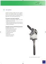
Use options Anatomic suspension implant with inner rotation. Thanks to the implant’s higher inner stability, it can be conveniently used for customized versions, especially in cases involving major bone loss. The implant is particularly suitable for: P ▪ atients with deformation changes and severe instability of the knee joint ▪ Patients with bone tumors in the knee area or major bone defects due to other causes (requiring implant customization) The implant comprises of the following component: (for details, see pp. 38–45): ▪ Femoral component, type CMS ▪ Tibial component, type CMS ▪ Articulation...
Open the catalog to page 3
Implant Description Surgical Technique ■ Surgical technique The surgical procedure starts with basic tibial resection. The individual steps during the operation consecutive phases are always the same, even in cases deviating from the recommended sequence of procedures. Subsequent partial steps: ■ preparation of the bone marrow section of the tibia ■ resection of the proximal end of the tibia and preparation thereof for the tibial component ■ cutting the bone marrow section of the femur ■ distal resection of the femur ■ setup of outer rotation of the femoral component ■ femoral resection (ventral,...
Open the catalog to page 4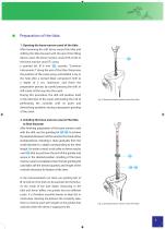
Preparation of the tibia 1. Opening the bone marrow canal of the tibia After loosening the soft tissue around the tibia and shifting the tibia forward with the aid of the lifting device, open the bone marrow canal. Drill a hole in the bone marrow canal (T) using a pointed bit, Ø 8 mm 158 , cassette "Common Instruments I" along the axis of the tibia. Determine the position of the canal using ventrodistal x-ray or the hole after a revised tibial component. Drill to a depth of 5 cm, maximum, and finish the preparation process by careful pressing the drill, in still mode, all the way into the canal....
Open the catalog to page 5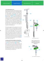
Implant Description Surgical Technique 3. Inserting centering rod Remember the diameter of the last grinder used for grinding the tibia. Now insert the assembled guiding rod that is used for anchoring and positioning of the intramedullary aiming device. The complete set consists of a bushing 173 - 178 of the guiding rod 169 and a head "T" 152 . The size of the bushing must match the size (diameter) of the last grinder used. To facilitate assembly of the set (especially bushing) it is suitable to use a trial bushing for the canal 168 , (see Fig. 4). Once the whole set of guiding rod is inserted,...
Open the catalog to page 6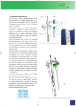
5. Preparation of tibial resection The next step involves complementation of the aiming device on the upper resection facet of the resection block with a gauge (0,-3) (J17. Set the point of the gauge (we recommend) on the tibia in the lowest position (see Fig. 7). Rotate the assembly slowly to set it in the right position, so that the axis of the resection block (depending on type of axial deformity) runs through the middle of tuberositas tibiae or slightly off the middle between it and the middle edge of tuberculum laterale of intercondylic eminence. Use the centering rod @) from the Common Instruments...
Open the catalog to page 7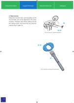
Implant Description Surgical Technique 6. Tibial resection Release the resection block, add the guiding rod for the saw blade, and cut the tibial facet to the extent necessary. Thereupon take off the guiding rod and the resection block, and extract the pins using the extractor (Fig. 34 , page 16). 186 - 187 Fig. 9: Securing of set - up tibial aming device Fig. 10: Assembly of centering matrix with handle
Open the catalog to page 8
7. Setting up rotation of tibial component First, assemble the tibial centering matrix 173 - 178 of the selected size (2–5) using the matrix handle 87 (see Fig. 10) Re-insert assembled guiding rod into the bone marrow canal, where it will be used as a centering and anchoring element for the centering matrix. Put the matrix on the guiding rod along with the handle and centering bushing 77 and then over the resection facet, so that the oval part fits into the hole in the matrix. Insert the centering rod from Common Instruments Cassette III 184 through the hole in the handle * and slowly rotate...
Open the catalog to page 9
Implant Description Surgical Technique 8. Preparation of canal for tibial component Put bushing 80 on the tibial centering matrix, so that the pins on the bottom side of the plate fit into unmarked holes in the matrix. Simultaneously, it is necessary to position the matrix as well as the headed fixation pins (both indentations on the side of the plate are designated for the head of the pin), see Fig. 13. Using a cone-shaped grinder bit 79 , prepare the canal for the stem of the tibial component (keep drilling until the grinder ring * touches the bushing) see Fig. 14. The final shape of the prepared...
Open the catalog to page 10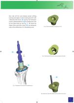
Now take off the cone-shaped grinder drilling bushing and replace it with a bushing for drill with a diameter of Ø 23 mm 81 (see Fig. 16). Thereupon use the cylindrical drill 0–23 78 to prepare the canal for the tibial facet jut (see Fig. 17, 18) Finish the shape of the canal with a chisel 167 , by making the sides of the drilled holes (19, 20) perfectly even. Fig. 18: Tibial canal drilled to a diameter of ∅ 23 Fig. 19: Final shape of the canal in the proximal part of the tibia Fig. 17: Preparation of the canal for the tibial facet jut Fig. 20: Make the sides of the drilled holes even with the...
Open the catalog to page 11
Implant Description Surgical Technique Preparation of the femur 9. Opening the bone marrow canal of the femur The drill for perforating the bone marrow canal (pointed bit) 158 to a diameter of 8 mm from the Common Instruments Cassette I. is driven along the femoral axis just above the upper end of the intercondylic incision, towards the middle or, better yet, more centrally by 5 mm (see Fig. 21). After drilling a hole to a depth of 4–5 cm, press the drill, in still mode, all the way into the canal. This way, the drill will find its position in the canal, diminishing the risk of the corticalis...
Open the catalog to page 12All Beznoska catalogs and technical brochures
 SKIN STAPLER 35W
1 Page
 Cementless cup – type SF
20 Pages
 Radial Head Replacement
12 Pages
 Humeral head resurfacing
12 Pages
 Hip Joint Head Replacements
8 Pages
 Cemented femoral stem - type CSC
16 Pages
 Hip Hemiarthroplasty – type CSB
20 Pages
 Cerclage System
12 Pages
 Implants for Traumatology
16 Pages
 Revision systems
32 Pages
 Implants for primary surgery
44 Pages
 Individual oncological implants
24 Pages


- Femoral stem
- Knee prosthesis
- Acetabular prosthesis
- Cementless femoral stem
- Cementless acetabular prosthesis
- Femoral head prosthesis
- Cemented femoral stem
- Fixed-bearing knee prosthesis
- Revision femoral stem
- Revision knee prosthesis
- Cemented knee prosthesis
- Cemented acetabular prosthesis
- Revision acetabular prosthesis
- Digit joint implant
- Tibial bearing
- Trapeziometacarpal joint implant