VISIO 5 ALARM UNIT

VISIO 5 ALARM UNIT
- VISIO 5 and VISIO 100: These models differ in logic and analog inputs, emergency battery duration, remote unit capacity, and data processing. VISIO 5 supports 5 logic inputs and 5 analog sensors, with a 1-hour emergency battery. VISIO 100 supports 4 logic inputs and 7 analog sensors but lacks an emergency battery.
- Recording and Alarms: VISIO 5 records the latest 99 events without a pre-alarm feature, while VISIO 100 includes a pre-alarm. Reset times differ between models.
- Connectivity: Both models use RS 232 - RS 485 for serial links and support 4-20mA sensors. VISIO 5 is programmed on board, whereas VISIO 100 can be programmed on board or via a global system control.
- Physical Characteristics: VISIO 5 is smaller and lighter than VISIO 100, with dimensions of 166x160x133 mm and a weight of 1.8 kg.
The VISIO system is designed to prevent defaults in medical gas networks, providing precise gas pressure information and secure traceability of failures. Qualified technicians offer optimization, installation, programming assistance, and training services.
- Available accessories include various sensors and mounting accessories, such as pressure and vacuum sensors, brass adapters, and mounting boxes.
The VISIO 5 unit can be wall-mounted and is equipped with connectors for easy installation. It requires a 230V power supply and uses SYT type cables for wiring. The unit is pre-programmed for a 4 secondary gas network.
- Features include alarm LEDs, power supply indicators, and buttons for cancellation and testing. The unit manages 5 logical/analogical inputs and displays gas pressures on an LCD.
Detailed instructions are provided for use, display, battery management, drilling size, electrical connections, and parameter settings. The document includes a table of contents and is updated as of 19/10/01.
Parameters can be modified via the LCD display and buttons. They are stored in EEPROM memory, ensuring retention even when the unit is powered off. The document provides a list of data addresses and parameters, including language settings, sensor types, and pressure values.
- The buzzer activates if a default persists beyond a specified period, with a maximum of 166 hours (7 days).
- Expected time values are provided for various durations, ranging from 15 minutes to 6 days.
- Parameters are listed for multiple inputs (ENT2 to ENT5), each with specific settings for CAP, MINI, MAXI, and TP values.
- Each parameter has a defined range, with original values provided for reference.
- In modification mode, users can change text using the U key and navigate with the D key.
- Authorized characters include space, numbers 0-9, and letters A-Z.
- Addresses TX1 to TX5 are reserved for future use, potentially for additional channels.
Catalog excerpts

CONTROL VISIO ASSISTANCE Our qualied technicians are at your disposal for: Electronics signals of medical gas networks by VISIO concept, (ISO 7396 – norm) is the solution to prevent any defaults of medical gas networks. This system gives precise information about the gas pressure, together with a secure traceability of the failures. The analogical technology of the sensors allows a great precision and a good stability. - Optimizing the different network congurations - Helping you with installation and programming - Finding any eventual connecting default - Training your technicians on system. Full free service (excluding external expenses in case) Direct line ACCESSORIES Waterproof analogical sensors provided with a cable of connecting and streamlined oxygen. Brass adapters for sensors mounting on the relaxation units and the pipes. Pressure sensor 0-16 atm ( G 1/4 ) Depression vacuum compact sensor 0-0.9 atm ( M 10 ) Reducer for compact sensors VAL 304 Mounting valve system for G 1/4 ( 250 atm only ) Mounting box for compact sensors SUPERVISION caracteristics Analogic ways (sensors) Emergency Battery Quantity of remote unit Data processing Networks pressures display Supply cuttingand error delays Logic pression Logic pression WALL UNIT INTEGRATION Wall integration VISIO 100 version allows a discreet integration of alarm system into a column or a depressurization box in the operating theatre or in the emergency units. The VISIOSOFT System is a powerful control software. Up to 27 alarms units, it allows to remote parameters of each alarm unit, centralization of the defaults on the same printer and analyses problem at distance. The alarm units are together connected and to the computer by BUS 485. The VISIOTEL interface dispatches the information by telephone for hospitals which are distant. On board or global system control Serie link 1 synthesis + 5 direct links Size - weight Wall Mounted / Integrated Box Emergency units Wall mounting
Open the catalog to page 1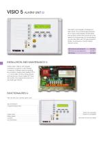
VISIO 5 ALARM UNIT Visio alarm unit manages 5 analogical or logic inputs. The concerned gas pressures are on liquid crystal display. Several green and red leds conrms the normal use or the default of concerned gas. By its polyvalence you can also either use it for gas production (bottle, compressors) or inside hospital network control. VISIO 5 alarm unit, wall mounted box VISIO 5 alarm unit, wall integrated box INSTALLATION AND MAINTENANCE Unibloc Alarm VISIO 5 with possible connection by bottom or rear. Release connectors of different sizes for avoiding any confusion. Supply power feeding 230...
Open the catalog to page 2
Installation Directions INSTALLATION DIRECTIONS
Open the catalog to page 3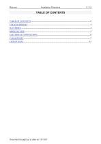
Installation Directions Document brought up to date on 19/10/01
Open the catalog to page 4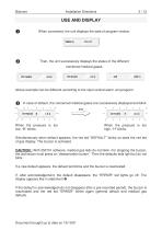
Installation Directions When connected, the unit displays the date of program version. 250701 Then, the unit successively displays the status of the different monitored medical gases. OXYGEN Above example can be different according to the input central alarm unit program. In case of default, the concerned medical gases are successively displayed and blink then When the pressure is too low, “B” blinks. When the pressure is too high, “H” blinks. Simultaneously when default appears, the red led “DEFAULT” blinks so does the red led of gas display. The buzzer is activated. CAUTION : With 250701 software,...
Open the catalog to page 5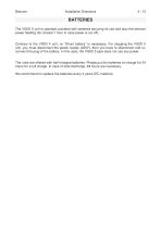
Installation Directions BATTERIES The VISIO 5 unit is standard provided with batteries securing its use and also the sensors power feeding (for at least 1 hour in case power is cut off). Contrary to the VISIO 4 unit, no “Shunt battery” is necessary. For stopping the VISIO 5 unit, you must disconnect the power supply (230V), then you have to disconnect and reconnect the plug of the battery. In this case, the VISIO 5 type does not use any power. The units are offered with half-charged batteries. Please put the batteries on charge for 24 hours for a full charge. In case of total discharge, 48 hours...
Open the catalog to page 6
Biolume Installation Directions 5/13 DRILLING SIZE
Open the catalog to page 7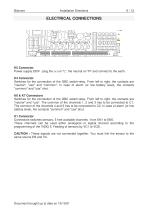
Installation Directions ELECTRICAL CONNECTIONS K5 Connector Power supply 230V : plug the (+) on "L", the neutral on "N" and connect to the earth. K4 Connector Switches for the connection of the GBC switch-relay. From left to right, the contacts are "neutral", "use" and "common". In case of alarm (or low battery level), the contacts "common" and "use" shut. K6 & K7 Connectors Switches for the connection of the GBC switch-relay. From left to right, the contacts are "neutral" and "use". The common of the channels 1, 2 and 3 has to be connected to C1. The common of the channels 4 and 5 has to be...
Open the catalog to page 8
Installation Directions PARAMETERS This chapter contains all information which will allow you to read, check and program and to adapt the use of the unit for a specific configuration in which it is installed. The parameters can be modified according to your requirements via the LCD display and the four buttons M, C, D and U. When the VISO 5 type is power supplied, pressing on one of the buttons switches on the display during 5 seconds. The parameters are recorded in an EEPROM memory (or E2PROM type), which keeps the information even when the VISIO 5 is totally out of supply. Every parameter is...
Open the catalog to page 9
Installation Directions Set the display to the 000 address by pressing simultaneously on CLEAR buttons. (the address 000 is not displayed, it is implicit recorded) Each press on U button adds 1 to Each press on D button adds 10 buttons resets the address to 000. The address 000 is automatically forced to 000 when the 4 buttons of parameters are not activated during one minute. This can be also done by pressing simultaneously on CLEAR No possible modification of parameter if supply feeding of the alarm is switch off. Each press on U button, increases by 1 the indicated value. Each press on D button,...
Open the catalog to page 10
Installation Directions Record the new parameter by pressing the VALID button simultaneously. If the value of the parameter is not correct, it is automatically modified. Or cancel the modification by pressing again on the MODIF buttons simultaneously By pressing on CLEAR buttons simultaneously, the program value is reset to 000 Choice from a list: The U button allows to change the choice from a list
Open the catalog to page 11All BIOLUME catalogs and technical brochures
 TECHNICAL UNITS
8 Pages
 RESINOR
19 Pages
 BIOLED bed head unit
4 Pages
 CANOPY LED LIGHTING CONCEPT
4 Pages
 BTL 2.0
4 Pages
 ERGO 602/302
1 Page
 BLUE BEETLE / EXOTIC GECKO
4 Pages
 VISIOTECH ALARM
4 Pages
 CERAH & MUSSE CONCEPTS
4 Pages
 BIOLINE
4 Pages
 BS 930
1 Page
 CANOPY
4 Pages
 COLIBRI
4 Pages
 LADY BIRD / BUTTERFLY
4 Pages
 ECOLINE
2 Pages
 ERGO 200
1 Page
 WHITE DOVE
1 Page
 ERGOLINE
3 Pages
 BTL
BTL2 Pages


- Bed head unit
- Wall-mounted bed head unit
- Bed head unit with light
- Horizontal bed head unit
- 1-station wash basin
- Patient room bed head unit
- Laboratory bench
- Intensive care medical supply system
- Medical hand wash basin
- Hygiene area hand wash basin
- Wall-mount wash basin
- Vertical bed head unit
- Supply beam system
- Cabinet unit
- ICU supply beam system
- Medical supply system with shelves
- Ceiling-mounted supply beam system
- Supply column
- Supply beam system with shelves
- 2-station hand wash basin