C55H1-01
1 /3Pages
C55H1-01
1 /3Pages
Catalog excerpts
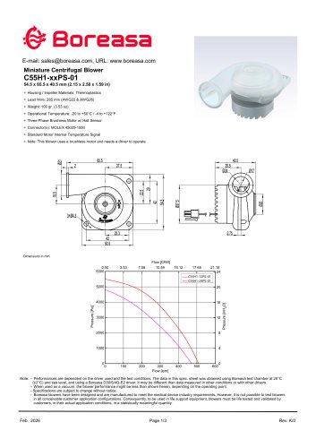
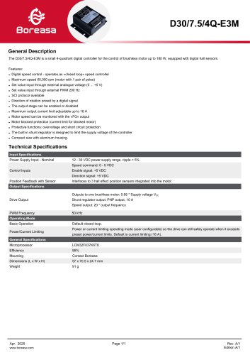
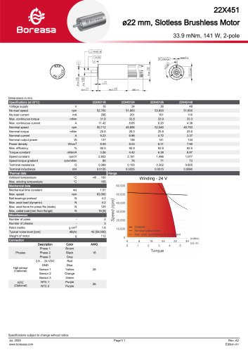
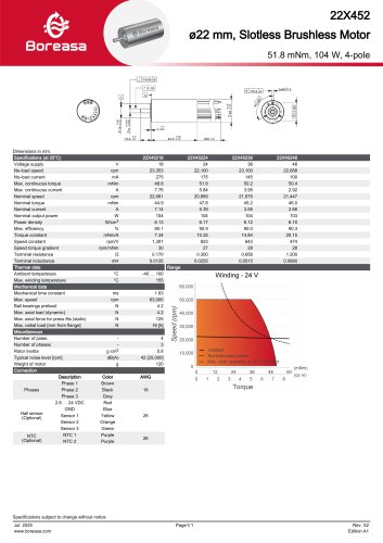
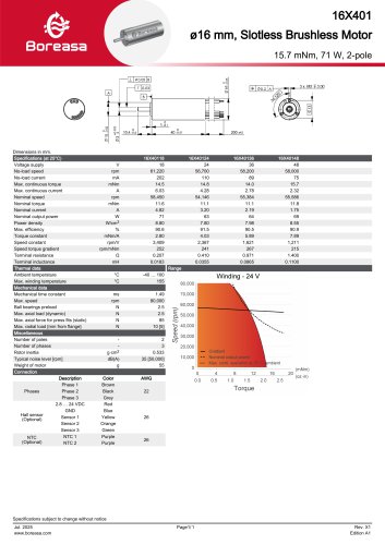
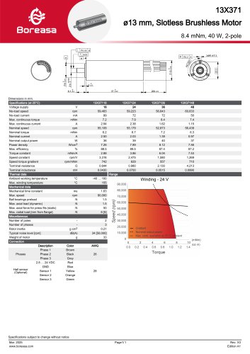
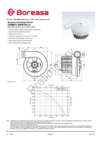
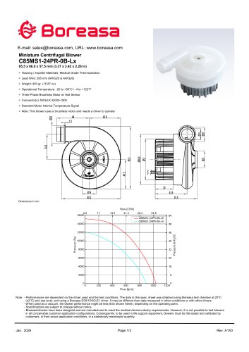
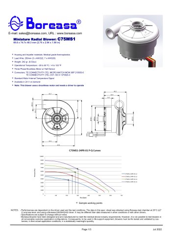
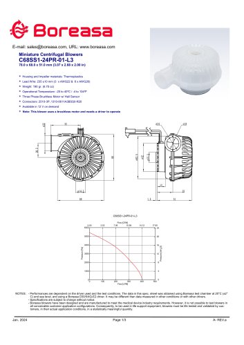
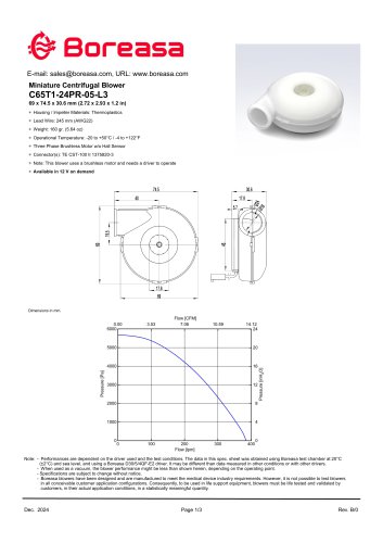
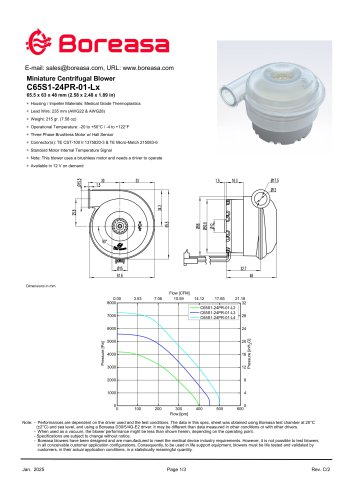
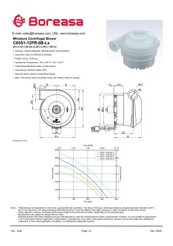
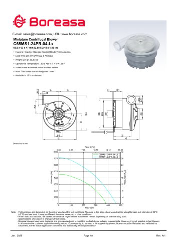
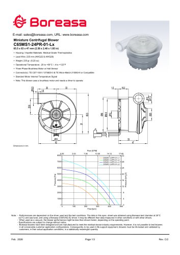
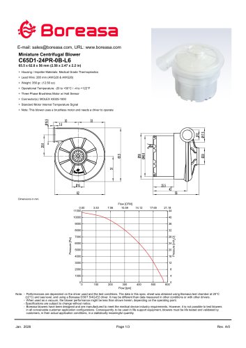
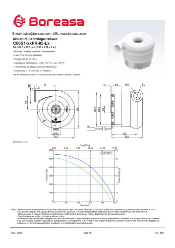
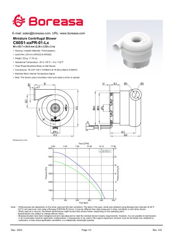
E-mail: [email protected], URL: www.boreasa.com Miniature Centrifugal Blower C55H1-xxPS-01 54.5 x 65.5 x 40.5 mm (2.15 x 2.58 x 1.59 in) ∗ Housing / Impeller Materials: Thermoplastics ∗ Lead Wire: 285 mm (AWG22 & AWG26) ∗ Weight: 100 gr. (3.53 oz) ∗ Operational Temperature: -20 to +50°C / -4 to +122°F ∗ Three Phase Brushless Motor w/ Hall Sensor ∗ Connector(s): MOLEX 43025-1000 ∗ Standard Motor Internal Temperature Signal ∗ Note: This blower uses a brushless motor and needs a driver to operate Note: - Performances are dependent on the driver used and the test conditions. The data in this spec. sheet was obtained using Boreasa test chamber at 20°C (±2°C) and sea level, and using a Boreasa D30/5/4Q-E2 driver. It may be different than data measured in other conditions or with other drivers. - When used as a vacuum, the blower performance might be less than shown herein, depending on the operating point. - Specifications are subject to change without notice. - Boreasa blowers have been designed and are manufactured to meet the medical device industry requirements. However, it is not possible to test blowers in all conceivable customer application configurations. Consequently, to be used in life support equipment, blowers must be life tested and validated by customers, in their actual application conditions, in a statistically meaningful quantity.
Open the catalog to page 1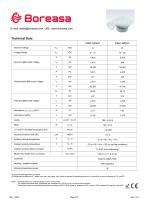
E-mail: [email protected], URL: www.boreasa.com #1 At given working points and cycle. #2 Measured at distance of 1 meter from inlet, with open inlet, outlet connected to breathing tube and 4 mm orifice in sound chamber at 10 cmH2O. N ote : - Working point is an example close to 50% of max. flow. - The phase inductance and impedance are measured by LCR at 1 kHz, including the connector. - Tolerances based on specified speed data according to ISO 13348, grade 4: pressure ±10%, power ±16%, speed ±5% and flow rate ±5%.
Open the catalog to page 2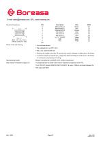
E-mail: [email protected], URL: www.boreasa.com Electrical Connections Rear side view shown (Mating connector side) Description Motorwinding U Motorwinding V Motorwinding W Hall sensor A Hall sensor B Hall sensor C VHall 3 ... 24 VDC GND NTC Wire Brown Blower Limits and Warning Manufacturing System Motor Internal Temperature Signal (IT) * Blocking the impeller more than 20 seconds may result in damages or destruction of the blower. * A minimum air flow is required at VCc higher than Nominal Voltage to avoid the air in the blower to overheat by compressing and mixing. Blowers manufactured by ISO9001-2015...
Open the catalog to page 3All Boreasa Technologies Co., Ltd catalogs and technical brochures
 D30/7.5/4Q-E3
1 Page
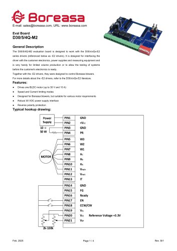 D30/5/4Q-M2
4 Pages
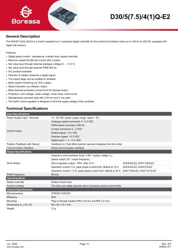 D30/5/4Q-E2
1 Page
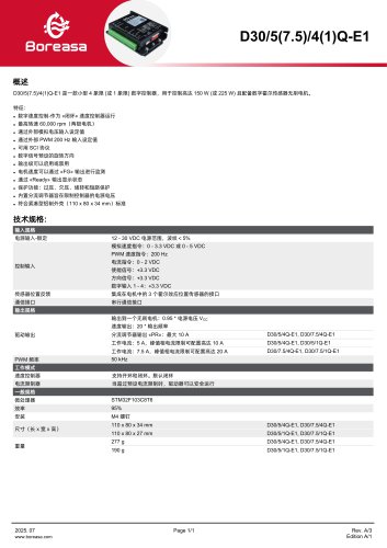 D30/5/4Q-E1
1 Page
 19X581
1 Page
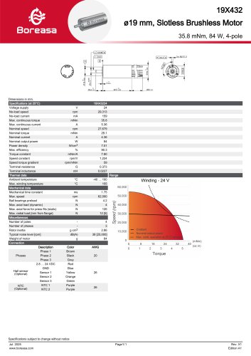 19X432
1 Page
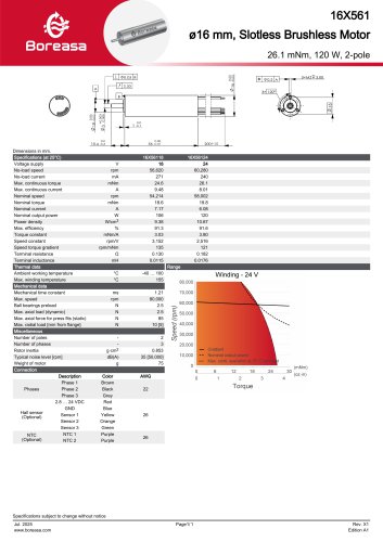 16X561
1 Page
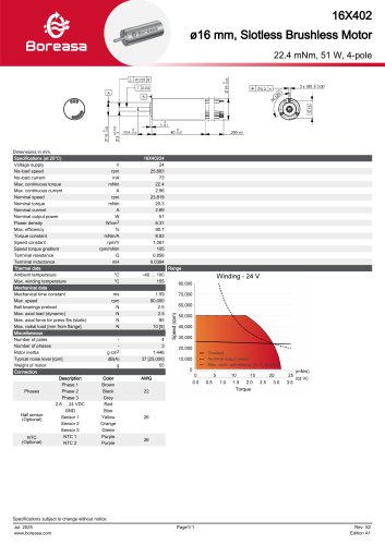 16X402
1 Page
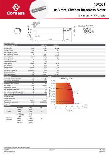 13X531
1 Page
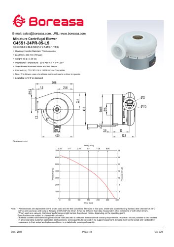 C45S1-24PR-05-L5
3 Pages
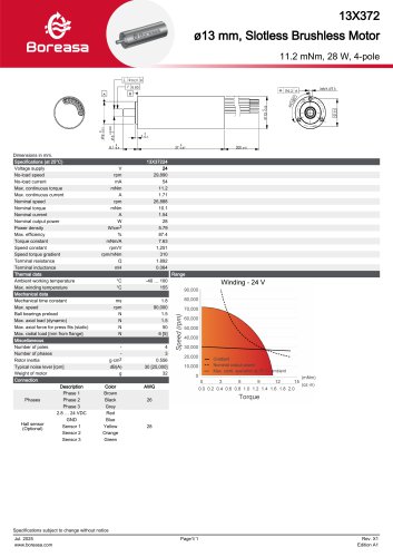 13X372
1 Page
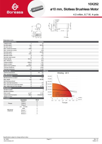 10X252
1 Page
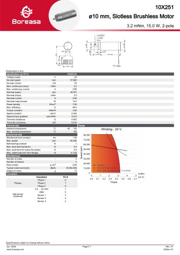 10X251
1 Page
 19 x 431
1 Page
 22 x 451
1 Page
 22 x 452
1 Page
 22 x 602
1 Page
 16 x 401
1 Page
 13 x 371
1 Page
 C85MS1-L5
4 Pages
 C85MS1-L4
3 Pages
 C75MS1
3 Pages
 C68SS1
3 Pages
 C65T1
C65T13 Pages
 C65S1
C65S13 Pages
 C65S1-0B
3 Pages
 C65MS1-04
4 Pages
 C65MS1
3 Pages
 C65D1
C65D13 Pages
 C60S1-04
3 Pages
 C60S1
C60S13 Pages
- Digital controller
- Boreasa Technologies medical industry motor
- Medical control system
- Boreasa Technologies DC motor
- Boreasa Technologies ventilator centrifugal blower
- Boreasa Technologies electronic ventilator centrifugal blower
- Boreasa Technologies home care ventilator centrifugal blower
- Boreasa Technologies compact ventilator centrifugal blower
- Boreasa Technologies CPAP ventilator centrifugal blower
- Boreasa Technologies clinical ventilator centrifugal blower
- Boreasa Technologies medical equipment motor
- Boreasa Technologies sleep apnea ventilator centrifugal blower
- Intensive care ventilator centrifugal blower
- Boreasa Technologies brushless motor ventilator centrifugal blower
- Boreasa Technologies medical ventilator motor
- Boreasa Technologies surgical power tool motor
- Portable ventilator centrifugal blower
- Boreasa Technologies silent ventilator centrifugal blower