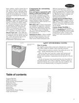
Overview: Carrier's 39M air handlers are versatile units designed for both indoor and outdoor applications, offering features that enhance flexibility, durability, and performance. They are easy to install and maintain, making them suitable for various air handling needs.
Key Features:- Protection and Installation: Units are shrink-wrapped for protection during transit and come with factory-supplied variable frequency drives. They require minimal tools for assembly.
- Design and Flexibility: Features include a sealed panel double-wall R-13 insulation system, space-efficient stacked configurations, and weathertight outdoor cabinets with sloped roofs.
- Performance and Efficiency: The AHUBuilder® software assists in unit selection and performance optimization. Units have low-leak dampers, efficient coil surfaces, and optional UV-C germicidal lamps for better indoor air quality.
- Customization Options: Available coil types include chilled water, direct expansion, hot water, and steam, with various filtration options. Units can be customized with factory-installed controls and components.
Benefits:- Durability: The design prevents insulation exposure to the airstream, and components like motors and drives are protected for longevity.
- Maintenance: Easily removable panels and doors facilitate cleaning and access, reducing maintenance time and effort.
- Energy and Cost Savings: Features like UV-C lamps and efficient coil designs contribute to energy savings and reduced operational costs.
Technical Specifications:- Airflow Capacity: 1,500 to 60,500 Nominal Cfm.
- Coil Options: Various configurations and materials, including copper and stainless steel, are available for different applications.
- Certification: Units are certified according to AHRI standards, ensuring reliable performance and quality.
Additional Features:- AgION® Anti-Microbial Coating: Provides long-term protection against microbial growth by releasing silver ions in humid conditions.
- Direct Digital Controls: Available for precise control and integration with building management systems.
Independent Zones and Filtration: Air handling units can create independent zones, each controlled by its own thermostat. High filtration units have a filter section before the cooling and heating coils and a final filter at the air entry point into the ductwork.
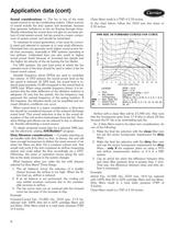
Fans: The 39M central station air handlers use belt-driven centrifugal fans, which can be double width, double inlet (DWDI) with forward curved or airfoil blades, or single width, single inlet (SWSI) with airfoil blades. Fan performance is predicted using fan laws, which relate airflow, pressure, horsepower, and fan size.
Fan Selection Criteria: Key factors in fan selection include airflow, static pressure, fan speed, brake horsepower, and sound level. Static pressure is influenced by system components and airflow requirements. Forward-curved fans may overload if actual static pressure is less than design pressure, while airfoil fans handle this better.
Stability and VAV Applications: Fan stability is crucial, with instability leading to system surge or fan stall. VAV systems require careful consideration to avoid operating points that lead to stall conditions.
Sound Considerations: Fans are major sound sources in air-conditioning systems. Proper sizing and selection can minimize sound levels. Variable frequency drives (VFDs) help reduce sound levels by modulating fan volume.
Dirty Filtration Considerations: Selecting air handlers with dirty filters ensures sufficient horsepower to maintain airflow. Adjustments may be needed to avoid motor overloads and ensure efficient operation.
Fan, Motor, and Drive Heat Considerations: Fan and motor efficiency losses translate into heat, affecting power requirements and cooling/heating loads. Calculations are provided to determine motor output and heat output.
Fan Application: Different fan types are suited for various pressure systems. Forward-curved fans are used for low to medium pressure applications, while airfoil fans are efficient at higher pressures. Plenum fans are used in medium to high static pressure applications.
Plenum Fans Overview: Plenum fans are designed for applications requiring discharge location flexibility, reduced discharge sound, and adaptability to changing duct configurations. They are less efficient than double-width, double-inlet airfoil fans and have a single-width, single-inlet construction. The fan shaft is parallel to the airflow, with the motor and bearings located inside the pressurized airstream. Plenum fans are ideal for spaces with limited room and where multiple duct connections are needed.
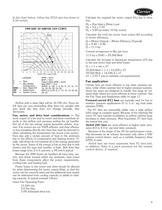
Pressure Loss Calculation: Pressure losses from plenum fan duct takeoffs can be calculated using the formula: Pl = Pp - Pd = (Cv) (Vp), where Pl is the pressure loss, Pp is the plenum pressure, Pd is the duct pressure, Cv is the pressure loss coefficient, and Vp is the velocity pressure in the duct. For radial duct takeoffs, Cv is 1.5 in. wg, and for axial duct takeoffs, Cv is 2.0 in. wg.
Duct Design Considerations: Proper duct design is crucial for fan performance. Straight discharge ductwork helps develop a uniform velocity profile and allows velocity pressure to recover into static pressure. For 100% recovery, the straight portion of the discharge duct must be at least 2.5 times the discharge diameter for velocities of 2500 fpm or less.
Fan Control on Variable Air Volume Systems: Variable air volume (VAV) systems reduce airflow to meet demand, saving energy. Effective fan control ensures proper duct pressure and quiet operation. Considerations include system parameters, fan type, motor selection, sound levels, and costs. Methods of fan air-volume control include terminal throttling and variable frequency drives (VFDs).
Fan Types and Applications: Forward-Curved (FC) Fans: Best for low to medium pressure applications, less expensive, and run at low speeds. Airfoil (AF) Fans: Suitable for high capacity and high-pressure applications, operate at high speeds, and are more expensive. Plenum (PAF) Fans: Ideal for limited space or multiple ducts, with characteristics similar to airfoil fans.
Variable Frequency Drives (VFDs): VFDs modulate fan motor speed in response to air volume requirements, offering energy savings and reduced sound levels. They convert input AC power to DC and then to a different AC output, requiring motors rated for inverter duty.
Supply Fan Control: In VAV systems, supply fan control matches fan delivery to airflow requirements by maintaining constant static pressure. VFDs are preferred over inlet guide vanes for efficiency and control over a larger airflow range.
Indoor Air Quality Applications: CO2 demand-controlled ventilation (DCV) increases minimum ventilation levels to maintain CO2 levels, achieving energy savings by ventilating only as needed.
Coil Definitions: Coils are heat exchange devices in air-handling equipment, transferring heat between a medium and the airstream. They consist of tubes, typically made of copper, and fins, usually made of aluminum, to enhance heat transfer efficiency.
Header and Casing: The header is a large diameter pipe distributing heating or cooling medium to tubes, typically made of non-ferrous metal or steel. The casing supports the tubes and header, usually made of galvanized steel or stainless steel.
Inlet and Outlet: These are pipe stubs on the header for medium entry and exit. Water coils use a counterflow arrangement, while steam coils have the inlet higher for condensate drainage.
Finned Area and Face Velocity: The finned area is the coil's working area, and face velocity is the air velocity across it. Maximum face velocity is determined to avoid moisture carryover, air pressure drop, and ensure heat transfer efficiency.
Tube Face and Pass: Tube face refers to the number of tubes in a coil row, with configurations available in 4, 6, 8, and 10 rows. A pass is a circuit part passing through the airstream once.
Direct Expansion Coils: These can have multiple refrigerant circuits for optimal performance. Circuit loading should be between 0.8 to 2.0 tons per circuit at design load.
Filters: Air filters are rated by efficiency and dust-holding capacity, following ASHRAE Standard 52.2 for MERV ratings.
Size Selection: The selection process involves determining airflow and preferred coil face velocity. Carrier's AHUBuilder program provides certified coil and performance data.
Selection Procedure: Charts are used to determine unit size based on airflow and face velocity. Different face velocity ranges are suggested for various applications.
Electric Heat Selection: Electric heat requirements are based on unit size, air quantity, and temperature rise. The heating load is calculated, and the appropriate electric heater size is selected.
Specifications: Top intake is not available on 39MW outdoor units. Mixing boxes feature double-wall, insulated, galvanized steel floors with various accessibility options including hinged double-wall access doors or removable panels. Exhaust boxes also have double-wall, insulated, galvanized steel floors with similar accessibility options.
Factory-Installed Options: Options include thermal pane reinforced glass viewports for mixing box sections and marine lights with or without convenience outlets.
Dampers: Mixing and exhaust boxes are equipped with parallel or opposed blades and interconnecting outside-air and return-air dampers. Standard dampers are made of galvanized steel with blade seals and stainless steel jamb seals, with a maximum leakage rate of 4 cfm/ft2 at 1 in. wg (0.25 kPa) differential pressure. Premium dampers have a double-skin airfoil design with a maximum leakage rate of 2 cfm/ft2.
Filtration: Filter mixing boxes accept 2-in. or 4-in. filters with side access slide rails. Angle filter sections are arranged in a horizontal V formation.
Air Mixer: Constructed of .081-in. aluminum, the air mixer is designed to mix air streams of differing temperatures to within ±6°F of the theoretical mixed-air temperature, ensuring uniform air velocity entering downstream filters or coil banks.
Dimensions and Weights: Dimensions and weights vary across unit sizes for both indoor (39MN) and outdoor (39MW) units. Key dimensions include height (H), width (W), airway length (AWL), duct depth (DA), and duct width (DW).
Coil Sections: All coil sections are of solid double-wall construction with galvanized steel inner and outer panels, carrying an R-value of no less than 13. Removable frame sections facilitate vertical coil extraction.
Specifications Overview: The document outlines specifications for various filter and coil sections used in HVAC systems. It includes details on dimensions, weight, and filter sizes for both indoor and outdoor units.
Filter Sections:- Draw-thru Bag/Cartridge Filter Sections: Capable of accepting 6-in. to 12-in. deep rigid media or bag filters. Accessibility options include hinged double-wall access doors or removable panels.
- Horizontal, Short Bag/Side Loading Cartridge Filter Section: Dimensions and weight vary by unit size, with specific configurations for indoor and outdoor units.
- Blow-thru Bag/Cartridge Filter Sections: Designed for face loading filter frames, accepting 12-in. deep rigid media or bag filters. Optional thermal pane reinforced glass viewports available.
- Blow-thru HEPA Filter Sections: Accepts 12-in. deep HEPA box filters with similar accessibility options as other sections.
Coil Sections:- Cooling Coil Section with Drain Pan: Features solid double-wall construction with insulation, removable frame sections, and sloped drain pans compliant with ASHRAE Standard 62.1-2010.
- Extended Length Cooling Coil Section: Similar construction and specifications as the standard cooling coil section, with extended length for larger applications.
- Heating Coil Section: Offers large, medium, and bypass coil face areas, with similar construction and accessibility options as cooling sections.
- Extended Length Heating Coil Section: Provides additional length for heating applications, maintaining the same construction standards.
- Dual Coil Section with Drain Pan: Designed for dual coil configurations, ensuring proper drainage and compliance with ASHRAE standards.
Key Parameters: Dimensions and weight are specified for each unit size, with variations between indoor (39MN) and outdoor (39MW) units. Filter sizes and face areas are detailed for each unit size, ensuring compatibility with different filter types. Accessibility options are consistent across sections, providing flexibility in installation and maintenance.
Recommendations: Ensure proper selection of filter and coil sections based on unit size and application requirements. Consider accessibility options for ease of maintenance and filter replacement. Adhere to ASHRAE standards for drainage and insulation to ensure system efficiency and compliance.
Specifications: The fan section is designed with a double-wall, insulated, galvanized steel floor. Accessibility options include hinged double-wall access doors on either or both sides, or removable double-wall access panels. Thermal pane reinforced glass viewports and marine lights with or without convenience outlets are available as factory-installed options.
Dimensions and Weight: Dimensions are provided for various unit sizes, with height (H), width (W), airway length (AWL), and weight specified for both indoor and outdoor units. The document includes detailed tables for vertical draw-thru supply fans, horizontal return fans, horizontal power exhaust fans, and plenum fans.
Fan Types and Options: The document outlines different fan types, including forward curve fans, airfoil fans, belt drive plenum fans, and direct drive plenum fans. Each fan type is associated with specific unit sizes and includes details on fan wheel, horsepower, and frame specifications.
Construction and Materials: Fan supports, structural members, panels, or flooring should not be welded unless using aluminum, stainless steel, or other corrosion-resistant materials. The fan airway length is based on standard diameter fans with top horizontal front discharge, and variations may affect dimensions.
Additional Notes: For precise dimensions and further fan detail options, the document refers to guide specifications on pages 83-110 and recommends consulting AHUBuilder® for exact measurements.
Overview: The document provides detailed specifications and guidelines for premium efficiency EISA compliant motors and HVAC systems, focusing on Open Drip Proof (ODP) and Totally Enclosed Fan Cooled (TEFC) motors, as well as central station air handler units.
Motor Specifications: The document lists full load amps (FLA) for various motor horsepower (HP) ratings across different voltages (208, 230, 460, 575) and their efficiency percentages. It distinguishes between ODP and TEFC motors, providing data for both 1800 RPM and 3600 RPM configurations. Key parameters include motor efficiency, NEMA frame sizes, and compliance with the Energy Independence and Security Act of 2007 (EISA).
Electrical Data: The document includes tables detailing the electrical characteristics of motors, such as FLA for 3-phase, 60 Hz voltages, and efficiency ratings. It emphasizes the importance of using copper wiring conforming to the National Electrical Code (NEC).
HVAC Guide Specifications: The guide covers the specifications for Carrier Model Number 39MN indoor units, detailing quality assurance, delivery, storage, protection, and start-up requirements. It specifies that units must be manufactured in ISO 9001 certified facilities and meet UL 1995 safety standards.
Product Details: The document outlines the construction and features of air-handling units, including casing construction, access doors, and drain pans. It specifies the use of galvanized steel, thermal breaks, and insulation standards. The guide also details fan specifications, including types, construction materials, and balancing standards.
Key Recommendations: The document recommends ensuring all wiring is copper and conforms to NEC standards. It also advises on proper handling and storage of units to prevent damage and ensure operational readiness.
Critical Information: The document highlights the importance of compliance with various standards, including AHRI, NFPA, and ASHRAE, to ensure safety, efficiency, and performance of the HVAC systems.
Integral Face and Bypass Dampers:- These dampers maintain constant air volume and temperature, with a variance of 5°F, regardless of damper position.
- When heating is not needed, air is diverted to bypass the heating surface.
- Constructed from galvanized or stainless steel, tested at 300 psig, and equipped for actuator connections.
Face and Bypass Dampers:- Internal dampers are factory-mounted with galvanized steel blades and seals, designed to prevent warping.
- External dampers also feature galvanized steel construction with stainless steel jamb seals.
Multi-Zone Dampers:- Factory-mounted with galvanized steel and double-skin airfoil design, ensuring minimal leakage and pressure drop.
Air Mixer:- Constructed from aluminum, it mixes air streams to achieve uniform temperature and velocity.
UV-C Germicidal Lamps:- Designed for HVAC systems, with a 1-year warranty, ensuring specific UV-C output and energy distribution.
Electrical Accessories:- Includes marine lights and convenience outlets, with weatherproof construction and UL listing.
- Disconnects are available in various voltage and phase configurations, with features like visible blades and quick-make mechanisms.
Starters and Bypass for Variable Frequency Drives:- Starters include overload protection and manual reset, with UL listing.
- Bypasses are designed for specific voltage and horsepower ranges, ensuring isolation and safety compliance.
Variable Frequency Drives (VFDs):- Factory-mounted and programmed, with a warranty and features like digital display, keypad, and built-in timeclock.
- VFDs are designed to operate under specific environmental conditions and include pre-programmed application macros.
Specifications: The document outlines the specifications for Variable Frequency Drives (VFDs) with features designed for easy maintenance and enhanced operational efficiency. Key specifications include:
- Cooling fans that operate only when necessary to extend their lifespan.
- Capability to start into a coasting load and accelerate or decelerate without tripping.
- Automatic restart after protective trips with programmable restart attempts.
- Overload ratings of 110% for 1 minute and 130% for 2 seconds.
- Internal 5% impedance reactors to reduce harmonics and protect from AC line transients.
- Input current rating not exceeding 3% more than the output current rating.
- AC transient surge protection system with MOVs, capacitor clamp, and reactors.
- Programmable loss-of-load relay output and underload/overload curve functions.
- Multiple PID algorithms for maintaining control from two feedback signals.
- Options for handling lost input references and programmable sleep/wake functions.
Adjustments and Controls: The VFDs include several programmable features for enhanced control:
- Three critical frequency lockout ranges to prevent unstable speeds.
- Two PID set point controllers for closed-loop control with auxiliary power.
- Independent second PID loop for additional process control.
- Programmable analog and digital inputs/outputs for flexibility.
- Run permissive circuit for damper or valve control with safety interlocks.
- Programmable start delay and preset speeds.
- Motor flux optimization and carrier frequency control for energy efficiency.
- Password protection against unauthorized parameter changes.
Keypad and Display: The VFDs feature a backlit LCD display with complete English words for programming and diagnostics. The keypad includes various assistants for setup and troubleshooting, and can display multiple operating values simultaneously.
Fireman’s Override and Serial Communications: The VFDs include a fireman’s override input for emergency operation and support multiple communication protocols like Modbus and BACnet. They offer extensive serial communication capabilities for monitoring and control.
EMI/RFI Filters and Protection: All VFDs include EMI/RFI filters for compliance with EN 61800-3 standards. They are protected from input/output power mis-wiring and include various operational functions and protective features to ensure reliability and safety.
Trip Detection and Error Codes: Various trip detections are outlined, including short circuit, overvoltage, overload, overheating, and EEPROM failures. Specific errors such as RAM, ROM, CPU, and communication interruptions are also listed.
Monitor Functions: The drive features a digital display for various metrics like frequency, current, voltage, RPM, and more. It includes 320 programmable parameters, adjustable via an 8-key touchpad or computer link, and offers reset options to factory or user defaults. The drive also supports programmable outputs and inputs.
Quality Assurance: Manufacturers must have at least 5 years of experience and comply with ISO 9001 standards. Units should have UL 1995 certification and meet AHRI and NFPA standards.
Delivery and Protection: Units must be shrink-wrapped for protection during shipment and stored in a clean, dry place. Proper handling is required to avoid damage.
Start-Up Requirements: Units should not be operated until all components are verified, lubricated, and tested.
Product Description: Units are shipped in sections or assembled, with various factory-installed components like mixing boxes, air mixers, and coil sections. The casing is constructed with galvanized steel and features thermal breaks and insulation.
Casing and Construction: The casing is designed for durability and minimal leakage, with options for access doors and panels. The roof is designed to prevent water infiltration.
Fans: Fans are constructed for continuous operation and are dynamically balanced. They are designed to meet specific AMCA class ratings and are protected against corrosion.
Additional Features: Includes options for access doors, drain pans, roof curbs, and hoods and louvers for air intake and exhaust.
Specifications: Fans are available up to 5 hp and must comply with AHRI Standard 430 for performance ratings. Sound ratings require submission of octave sound power for fan discharge and casing radiated sound. Fans must be mounted on a common base assembly with factory-installed isolators and vibration absorbent seals.
Fan Accessories: Various accessories are specified for different fan types, including variable frequency drives, magnetic motor starters, motor disconnects, belt guards, and inlet screens.
Bearings and Drives: Bearings must be self-aligning, grease lubricated, and anti-friction, with extended lubrication fittings. Fan shafts should be solid steel, and V-belt drives must have a minimum 1.2 service factor.
Coils: All coils must meet AHRI Standard 410 and be tested at 450 psig air pressure. Coils are available in various configurations, including water, steam, and direct expansion types, with specific material and construction requirements.
Electric Heating Section: Electric heaters must be UL listed and meet NEC requirements, with specific construction and control options.
Humidifiers: Humidifiers are direct discharge type, using steam for humidification, with specific construction and material requirements.
Filter Sections: Filter sections must accommodate various filter sizes and configurations, with specific construction requirements.
Dampers: Dampers must be warranted for 12 months and constructed with specific materials and design features to ensure minimal leakage.
Specifications: Coils are available in stainless steel and must be tested at 300 psig. Integral face and bypass coils should have a connection point for actuators, which can be electrical or pneumatic, and may be factory-provided at an additional cost. Internal face and bypass dampers are factory-mounted in galvanized steel frames with high-temperature seals. Dampers are sectionalized to prevent warping and are interconnected for simultaneous operation.
Air Mixer: The air mixer is constructed from 0.081-inch aluminum and is designed to mix air streams of differing temperatures to within ±6°F of the theoretical mixed-air temperature.
UV-C Germicidal Lamps: Designed for HVAC systems with a 1-year warranty. Lamp output is measured at 253.7 nm and should not be less than 10 μW/cm² per inch of arc length. Power supplies are high-efficiency electronic types, matched to emitters, and should not exceed 80 watts input power. Fixtures are factory-installed and wired with safety switches. Lamps are shipped separately to prevent damage. UV-C energy distribution must be even across the coil and drain pan, with a minimum energy level of 820 μW/cm² at the closest point.
Electrical Accessories: Marine Lights and Convenience Outlets: Weatherproof fixtures with a 100-watt capacity and equipped with a long-life lamp. Includes a weatherproof switch enclosure and GFCI receptacle.
Disconnects: Non-fused and fused disconnects are available with various voltage and phase options, featuring corrosion protection, grounding terminals, and UL listing. Fused disconnects include visible blades and quick-make, quick-break mechanisms.
Starters: Starters include adjustable motor overloads, manual reset buttons, and are UL listed. Combination starters include a non-fused disconnect switch and are factory-mounted and tested.
Bypass for Variable Frequency Drives (VFDs): Bypasses are available for various voltage and horsepower ratings, featuring lockable handles and switch position indications. They provide complete isolation of the inverter in the LINE position and are UL listed.
Variable Frequency Drives (VFDs): Factory-mounted and wired to motors, VFDs come with a 24-month warranty from commissioning. VFDs are programmed with parameters for easy replacement and feature environmental operating conditions suitable for a wide range of temperatures and altitudes. Standard features include a digital display, keypad, timeclock, and application macros for easy start-up. VFDs have internal reactors to reduce harmonics and protect from AC line transients.
Specifications: The document outlines the specifications for Variable Frequency Drives (VFDs), emphasizing the need for input and output current ratings on the VFD nameplate. It includes requirements for AC transient surge protection, programmable loss-of-load detection, and user-programmable underload and overload functions. The VFD must support multiple PID algorithms for control from two separate feedback signals and provide options if input references are lost.
Procedures: The VFD should have programmable sleep and wake-up functions, critical frequency lockout ranges, and PID set point controllers. It must support two independent PID loops and have programmable analog and digital inputs and outputs. The VFD should include a run permissive circuit for damper or valve control and a programmable start delay.
Norms and Standards: The VFD must comply with EMI/RFI filtering standards, allowing CE marking and meeting EN 61800-3 standards. It should be protected from input and output power mis-wiring and include a fireman’s override input.
Recommandations: Operational functions should include separate acceleration/deceleration times, local/remote keys, and a quick setup key. The drive should support storable custom user settings and adjustable soft stall features. Protective features include a high ampere interrupting capacity, external fault input, and programmable alarms for various fault conditions.
Key Features: The VFD should have a backlit LCD display with English words for programming and diagnostics, supporting multiple assistants for setup and troubleshooting. It should display key operating values in user units and include serial communication capabilities with standard protocols like Modbus and BACnet.
Protective Features: The drive should alert users to over torque, inverter overload, motor overload, and other pre-alarms. It should identify and display faults such as overcurrent, overvoltage, and EEPROM errors.
Monitor Functions: The digital display should show frequency, current, voltage, RPM, and other metrics. The drive should have numerous programmable parameters adjustable via a touchpad or computer link.
Specifications: The system must include a reset function for all parameters, allowing for either factory default settings or user-defined defaults. It should feature two programmable analog outputs with 17 configuration options. There must be one programmable relay output with 67 configuration options. The system should include eight programmable digital inputs with 54 configuration options. A pulse train output proportional to frequency should be available, with options for 48, 96, or 360 times the frequency. An elapsed time meter is required.


 WeatherMaker® 50TCQ
 INFINITY™ 38MPRA
 ActivAIR™ 36CB
 ACTIVAIR™ 36IB
 Axis™
Axis™
 50ZPB
50ZPB AHUBuilder
 PERFORMANCE™ 50VT-A
 Carrier® Ductless Systems
 PERFORMANCE™ 50VL-A
 Axis™ Overhead Air Terminals
 ActivAIR™ Induction Beams
 39CC
39CC A World of Comfort
 Aero® 39M Air Handlers
 17DA Centrifugal Chiller
 Air Handling Units 39 HQ
 48XL-A
 48VL Performance? 14
 48TC WEATHERMAKER®
 48LC WEATHEREXPERT®
 48HC WEATHERMASTER®
 48PM CENTURION?
 48PG CENTURION?
 48A WEATHERMAKER®
 48P WEATHERMASTER®
 48XL Infinity? 15
 OMNIZONE?
 39L AERO®
 30RAP AQUASNAP®
 39S
39S 30RB AQUASNAP®
 EVERGREEN® 23XRV
 AQUAFORCE® 30XA
 AQUAFORCE® 30XW150-400
 EVERGREEN® 30HXA,HXC076-271
 16TJ
16TJ AQUASNAP® 30MPA,MPW015-045
 19XR EVERGREEN®
 Aero Air-Handling Units


