
- Catalogs
- Carrier| Commercial Systems North America
- 48A WEATHERMAKER®


48A WEATHERMAKER®

48A WEATHERMAKER®
- Environmentally Sound Refrigerant: Utilizes Puron (R-410A), an HFC refrigerant that is non-ozone depleting.
- ComfortLink Controls: Provides easy-to-use, plain language display and integration with building systems via BACnet, MODBUS, or LonWorks protocols.
- Design Flexibility: Available in vertical and horizontal configurations, suitable for new constructions or retrofits.
- Energy Efficiency: Meets ASHRAE Standard 90.1-2010 with high EERs and supports variable frequency drive (VFD) for energy savings.
- Reliability: Features multiple scroll compressors, independent refrigerant circuits, and robust microchannel coils.
- Electrical Characteristics: 460-3-60
- Unit Type: Gas Heating Vertical Discharge
- Cooling Capacity: Select the unit based on required cooling capacity. For a condenser entering temperature of 95°F, unit 48A3D040 at 16,000 cfm and 67°F ewb provides a total capacity of 485,000 Btuh and a sensible heat capacity (SHC) of 380,000 Btuh.
- Heat Capacity: Unit 48A3D040 provides 324,000 Btuh with an input of 400,000 Btuh.
- Supply Fan: At 1.4 in. wg and 16,000 cfm, the fan speed is 1063 rpm, requiring 19.06 bhp. A 20 hp motor is necessary.
- Power Source: Ensure the unit corresponds to the available power source, which is 460-3-60.
- Options and Accessories: In dry climates, an economizer is required per ASHRAE 90.1. Options include differential dry bulb changeover, outdoor air changeover, or differential enthalpy, but not outside air enthalpy.
1. Fan performance is based on wet coils, economizer, roof curb, cabinet losses, and clean 2-in. filters.
2. Variable air volume units can operate down to 70 cfm/ton, with performance limitations under certain conditions.
1. Multiple Stage Evaporator Discharge Temperature (EDT): Utilizes an adaptive PID algorithm to control economizer and compressor capacity based on evaporator air discharge and supply air temperature set points.
2. Multiple Adaptive Demand: Adjusts capacity using evaporator air discharge temperature and supply air temperature set points, with modes for LOW COOL and HIGH COOL.
3. Two-Stage Demand: Operates with integrated economizer and two stages of compressor capacity control.
4. Integrated Economizer: Delays mechanical cooling to maximize free cooling, supplementing as needed.
1. Two-Stage Control: Operates in LOW or HIGH HEAT mode based on demand inputs.
2. Multiple-Stage Control: Adjusts heating capacity based on set point and supply-air temperature, with staged gas control logic.
3. Tempering Mode: Used during ventilation or cooling modes to prevent low temperature air delivery.
1. Economizer Modes: Supports outdoor air dry bulb, differential dry bulb, outdoor air enthalpy, differential enthalpy, and outdoor air dew point changeover.
2. Building Pressure Control: Includes relief dampers, non-modulating two-stage power exhaust, and modulating power exhaust.
3. Indoor Air Quality (IAQ): Modulates outside air damper position based on space CO2 levels, with optional outdoor air quality sensor integration.
Includes optional return air smoke detector and supports smoke control modes like evacuation, smoke purge, and pressurization.
Supports fixed or variable capacity limits through discrete input switches or analog input signals.
Advanced diagnostics and prognostics with adaptive logic, storing last 10 alarms, and monitoring through Carrier Comfort Network®.
Interfaces with i-Vu® Open Control System, BACnet, and other energy management systems. Provides multiple contact connection points for external controls.
Designed for CV/SAV™ applications, operable as stand-alone units with standard or programmable thermostats, or electronic room temperature sensors.
- Induced-draft combustion with energy-saving direct spark ignition and redundant main gas valves.
- Heat exchanger made of 20-gage steel with aluminum-silicone alloy coating for corrosion resistance; optional stainless steel available.
- In-shot type burners made of aluminum-coated steel.
- Single location gas piping entry.
- Induced draft fans are direct-driven, single inlet, forward-curved centrifugal type, balanced and corrosion-resistant.
- High-corrosion areas lined with corrosion-resistant material.
- Dual refrigerant circuits with solid core filter drier, thermostatic expansion valve, and fusible plug.
- Standard 2-inch thick disposable fiberglass filters.
- ComfortLink Controls with scrolling display, CCN capable, and various safety features including compressor lockout and protection mechanisms.
- Automatic compressor lead/lag control and service diagnostic mode.
- Optional integrated economizer control and multiple capacity stages.
- Capable of starting and running at 115°F ambient temperature.
- Operates in cooling down to 32°F outdoor temperature.
- Fan time delay to prevent cold air delivery.
- Single location power wiring entry.
- Compressor motors cooled by refrigerant gas with overload protection.
- Condenser-fan motors are totally enclosed, 3-phase type with thermal overload protection.
- Indoor fan and power exhaust motors meet EISA 2007 efficiency requirements.
- Integrated Economizer meeting ASHRAE 90.1 requirements.
- Barometric Relief Damper Package and Power Exhaust for pressure control.
- Various optional features including thermostats, CO2 sensors, smoke detectors, and more.
- Outdoor roof curb or slab mounted unit with hermetic scroll compressors for cooling and gas/electric heating.
- Meets ASHRAE Standard 90.1-2010 EER requirements.
- Rated in accordance with AHRI Standard 340/360.
- Conforms to ANSI/ASHRAE and UL standards.
- Manufactured in ISO 9001 registered facility.
- Follow manufacturer’s recommendations.
- Factory-assembled unit with all necessary components and features for field start-up.
- Unit cabinet constructed of galvanized steel with baked enamel finish and insulated access panels.
- Fans include indoor evaporator and condenser fans with specific construction and balancing requirements.
The VFD is factory-installed inside the unit cabinet, controlling motor speed to maintain static pressure at the supply duct. It features full digital control, IGBT for quiet operation, self-diagnostics, security lockout, and RS485 capability. It includes electronic thermal overload protection and harmonic reduction features.
Fully hermetic scroll type with overload and short cycle protection, vibration isolation, and reverse rotation protection. Crankcase heaters activate only during off mode.
Evaporator coils have aluminum fins bonded to copper tubes, while condenser coils are microchannel design. Coils are leak and pressure tested. Optional coatings are available for corrosion resistance.
Features induced-draft combustion with direct spark ignition and redundant gas valves. Heat exchangers are corrosion-resistant, and burners are aluminum-coated steel.
Includes dual refrigerant circuits with solid core filter drier, thermostatic expansion valve, and fusible plug.
Standard filters are 2-inch thick disposable fiberglass.
ComfortLink controls with scrolling display, CCN capability, and various safety features including compressor lockout and protection against high/low pressure and freeze conditions.
Capable of operating at 115°F and cooling down to 32°F. Includes fan time delay to prevent cold air delivery.
All power wiring enters at a single location.
Compressor motors are refrigerant-cooled with overload protection. Condenser-fan motors are enclosed with thermal overload protection.
Includes options like integrated economizer, power exhaust, propane conversion kit, convenience outlet, and various sensors and communication options.
Specifications and designs are subject to change without notice.
Catalog excerpts
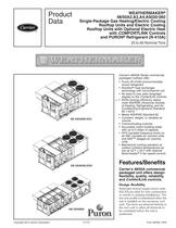
Product Data WEATHERMAKER® 48/50A2,A3,A4,A5020-060 Single-Package Gas Heating/Electric Cooling Rooftop Units and Electric Cooling Rooftop Units with Optional Electric Heat with COMFORTLINK Controls and PURON® Refrigerant (R-410A) 20 to 60 Nominal Tons Carrier’s 48/50A Series commercial packaged rooftops offer: • Puron (R-410A) environmentally sound refrigerant • Novation® heat exchanger technology with microchannel coil • An easy-to-use, plain language display on the ComfortLink controls • EERs (energy efficiency ratios) meet ASHRAE (American Society of Heating, Refrigerating, and Air Conditioning Engineers) Standard 90.1-2010 • Meets ASHRAE Standard 62 • Constant, staged, or variable air volume • Communicating controls • Accurately match building loads with up to 5 steps of capacity • VFD (variable frequency drive) on all VAV (variable air volume) units and SAV™ (staged air volume) units • Mechanical cooling operation at outdoor ambient temperatures as low as 32 F (–20 F with optional Motormaster® V fan speed control) Carrier’s 48/50A commercial packaged unit offers design flexibility, quality, reliability, and ComfortLink controls. a48-8351 Copyright 2012 Carrier Corporation Design flexibility Dedicated vertical supply/return units (A2,A3) are ideal for new construction or retrofit to existing installations. The low unit profile is maintained when the unit is installed on the accessory roof curb. The ducts are attached directly to the roof curb to allow all ductwork to be completed before the unit is positioned. Form 48/50A-13PD
Open the catalog to page 1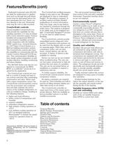
Features/Benefits (cont) Dedicated horizontal units (A4,A5) are ideal for replacement or applications such as through-the-wall where sound must be attenuated before the duct penetrates the roof. Ducts connect directly to the unit. Horizontal units may be curb or slab mounted. ComfortLink controls Factory-installed ComfortLink controls provide the capability for free standing operation or it may be linked with a more extensive system. Factoryinstalled and programmed BACnet* communication capability provides simple integration with the building HVAC system (e.g., terminal devices), an i-Vu® Open...
Open the catalog to page 2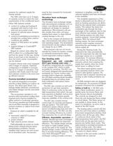
pressure for optimum supply fan energy savings. The VAV units have up to 5 stages of capacity control to match the load requirements of the conditioned space. Other VAV features include: • control of cooling and heating (if equipped with heat) in both occupied and unoccupied mode • support of optional space temperature sensor • control of modulating economizer to provide free cooling when outdoor conditions are suitable • support of IAQ (indoor air quality) sensor • support linkage to ComfortID™ VAV systems Staged air volume units utilize the VFD to allow for a configurable high and low fan speed....
Open the catalog to page 3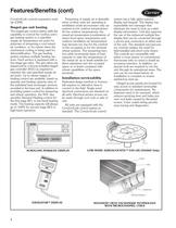
Features/Benefits (cont) ComfortLink controls expansion module (CEM). Staged gas unit heating The staged gas control option adds the capability to control the rooftop unit’s gas heating system to a specified supply air temperature set point for purposes of tempering a cool mixedair condition, or for reheat when the mechanical cooling is being used for dehumidification. The gas heating system employs multiple heating sections. Each section is equipped with a two-stage gas valve. The gas valves are sequenced by a factory-installed staged gas controller (SGC) as required to maintain the user-specified...
Open the catalog to page 4
Model number nomenclature 48A2,A3,A4,A5 UNITS 48 48 – Cooling Unit with Gas Heat Configuration A2 – CV/SAV Vertical with ComfortLink Controls and Puron® Refrigerant (R-410A) A3 – VAV Vertical with ComfortLink Controls and Puron Refrigerant (R-410A) A4 – CV/SAV Horizontal with ComfortLink Controls and Puron Refrigerant (R-410A) A5 – VAV Horizontal with ComfortLink Controls and Puron Refrigerant (R-410A) Heat Options D – Low Gas Heat E – High Gas Heat M – Low Gas Heat Stainless N – High Gas Heat Stainless S – Staged Low Gas Heat Stainless T – Staged High Gas Heat Stainless Unit Size - Nominal Tons...
Open the catalog to page 5
Model number nomenclature (cont) 50A2,A3,A4,A5 UNITS 50 Factory-Installed Options Refer to price pages for available option codes. Configuration A2 – CV/SAV Vertical with ComfortLink Controls and Puron® Refrigerant (R-410A) A3 – VAV Vertical with ComfortLink Controls and Puron Refrigerant (R-410A) A4 – CV/SAV Horizontal with ComfortLink Controls and Puron Refrigerant (R-410A) A5 – VAV Horizontal with ComfortLink Controls and Puron Refrigerant (R-410A) Packaging/Communication 1 – Domestic 3 – Export A – Domestic with BACnet Communication Option C – Export with BACnet Communication Option Heat...
Open the catalog to page 6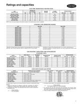
Ratings and capacities ELECTRIC RESISTANCE HEATER DATA UNIT 50A2,A3,A4,A5 020-035 LO HEAT 020-035 HIGH HEAT 040,050 LO HEAT 040,050 HIGH HEAT 060 LO HEAT 060 HIGH HEAT DESIGN RANGE NOTE: Due to the open design of the electric heaters, the airside pressure drop is negligible. *Operation at these levels may be limited by entering evaporator air wet bulb temperatures. See Cooling Capacities tables on pages 39-46 for further details. MAX CFM* 10,000 10,000 12,500 12,500 13,500 13,500 15,000 15,000 17,500 17,500 20,000 20,000 20,000 20,000 27,000 27,000 †Variable air volume units will operate down...
Open the catalog to page 7
Ratings and capacities (cont) CAPACITY CONTROL STAGING OPTIONS DEMAND SOURCE SAV/CV, Mech Thermostat COMPRESSOR SEQUENCE SIZE 020-027 UNITS SIZE 030-060 UNITS WITHOUT WITH WITHOUT WITH HOT GAS HOT GAS HOT GAS HOT GAS BYPASS BYPASS BYPASS BYPASS Table C Table D Table E Table F Table C Table D Table E Table F Table A NA Table B NA Table C Table D Table E Table F Table A NA Table B NA Table C Table D Table E Table F COOLING CONTROL METHOD Multiple Stage EDT Multiple Stage EDT 2 Stage Demand Multiple Adaptive Demand 2 Stage Demand Multiple Adaptive Demand LEGEND Constant Volume Evaporator Discharge...
Open the catalog to page 8All Carrier| Commercial Systems North America catalogs and technical brochures
 WeatherMaker® 50TCQ
116 Pages
 INFINITY™ 38MPRA
2 Pages
 ActivAIR™ 36CB
24 Pages
 ACTIVAIR™ 36IB
44 Pages
 Axis™
Axis™2 Pages

Archived catalogs
 50ZPB
50ZPB4 Pages
 AHUBuilder
2 Pages
 PERFORMANCE™ 50VT-A
6 Pages
 Carrier® Ductless Systems
8 Pages
 PERFORMANCE™ 50VL-A
6 Pages
 Axis™ Overhead Air Terminals
2 Pages
 ActivAIR™ Induction Beams
2 Pages
 39CC
39CC2 Pages
 A World of Comfort
2 Pages
 Aero® 39M Air Handlers
2 Pages
 17DA Centrifugal Chiller
2 Pages
 Air Handling Units 39 HQ
6 Pages
 48XL-A
30 Pages
 48VL Performance? 14
32 Pages
 48TC WEATHERMAKER®
116 Pages
 48LC WEATHEREXPERT®
52 Pages
 48HC WEATHERMASTER®
124 Pages
 48PM CENTURION?
64 Pages
 48PG CENTURION?
107 Pages
 48P WEATHERMASTER®
168 Pages
 48XL Infinity? 15
26 Pages
 OMNIZONE?
80 Pages
 39L AERO®
52 Pages
 30RAP AQUASNAP®
88 Pages
 39S
39S36 Pages
 30RB AQUASNAP®
92 Pages
 EVERGREEN® 23XRV
32 Pages
 AQUAFORCE® 30XA
150 Pages
 AQUAFORCE® 30XW150-400
60 Pages
 EVERGREEN® 30HXA,HXC076-271
52 Pages
 16TJ
16TJ32 Pages
 AQUASNAP® 30MPA,MPW015-045
36 Pages
 39M AERO®
110 Pages
 19XR EVERGREEN®
56 Pages
 Aero Air-Handling Units
2 Pages


- Medical sensor
- Digital thermoregulator
- Cooling thermostat
- Heating thermostat
- Humidity sensor
- Cleanroom air handling unit
- Air-cooled water chiller
- Modular air handling unit
- Thermostat with touchscreen
- Water-cooled water chiller
- Ceiling-mounted fan coil unit
- Wall-mounted fan coil unit
- Floor-mounted fan coil unit
- Air/air heat pump
- Geothermal heat pump