
- Catalogs
- Carrier| Commercial Systems North America
- AQUAFORCE® 30XW150-400


AQUAFORCE® 30XW150-400

AQUAFORCE® 30XW150-400
- Uses chlorine-free R-134a HFC refrigerant.
- Equipped with positive displacement, twin screw compressors.
- AHRI certified efficiencies with IPLV as low as 0.472 kW per ton.
- Compact design with a width of less than 48 inches for easy installation.
- Dual independent refrigerant circuits for sizes 325-400, enhancing reliability and redundancy.
- Easy installation with single point power connection and quick piping connections.
- High efficiency meeting ASHRAE 90.1 2007 and CSA standards.
- Designed for both full load and part load operations, optimizing energy savings.
- Environmentally friendly with non-ozone depleting refrigerant.
- Positive displacement screw compression ensures stable operation.
- Factory tested for reliable start-up.
- Low starting current reduces overall current draw by up to 40%.
- Capable of providing up to 140°F leaving condenser water in heat recovery applications.
- Microprocessor controls available in multiple languages, enhancing reliability and reducing operational costs.
- Features like automatic capacity override, chilled liquid reset, and demand limiting improve efficiency and control.
- Optional refrigerant isolation valves and suction service valves for easier maintenance.
- Marine container shipment capability reduces shipping costs.
- ASME certified heat exchangers ensure safety and reliability.
- Units 150-300 are available with single point power connections.
- TB5 terminals are designated for various external connections, including remote on-off, chilled water pump interlock, and alarm relay, all requiring dry circuit applications capable of handling a 24-vac load up to 50 mA.
- Control of chilled water pumps requires normally open contacts from a field-supplied pump starter relay.
- TB6 is used for energy management board options, with specific ratings for occupancy override, demand limit, and ice done options.
- Chillers and starters should be stored indoors, protected from dirt and moisture, with specific temperature and humidity conditions maintained.
- Units should be installed indoors on a level surface, with adequate clearance for service and local code requirements.
- Relief valve vent lines must comply with local codes, and strainers with a minimum screen size of 20 mesh should be installed near inlet pipe connections.
- Avoid oversizing chillers by more than 15% at design conditions to prevent inefficiency.
- Maximum and minimum fluid temperatures for operation are specified, with recommendations for antifreeze solutions in brine applications.
- Evaporator flow rates must be managed according to specified ranges, with options for recirculation and bypass flow to maintain pressure drop within limits.
- Variable evaporator flow rates are permissible, but changes in flow and load should not exceed 10% per minute.
- Water loop volume must meet minimum requirements for temperature stability, with recommendations for tank installation to prevent stratification.
- Condenser fluid temperatures should be managed to optimize performance, with specific recommendations for flow control when temperatures drop below 65 F (18.3 C).
- Multiple chillers can be installed in parallel or series, with specific control and piping recommendations to ensure proper flow and efficiency.
- Dual chiller control allows for redundancy and better low load control, with communication links required between chillers.
- Energy management practices, such as demand limiting and temperature reset, can reduce operating costs.
- Remote on-off control can be implemented through hard-wired connections or the Carrier Comfort Network® system.
1. The system uses a microprocessor-controlled water-cooled liquid chiller with screw compressors and electronic expansion valves.
2. The unit is rated according to AHRI Standard 550/590 and complies with ASHRAE 15 Safety Code, NEC, and ASME codes.
3. Units are manufactured in ISO 9001 certified facilities and tested to UL or UL Canada standards.
4. Maximum wire size for terminal blocks is 500 kcmil, and copper conductors are required.
5. Maximum allowable phase imbalance is 2% for voltage and 5% for amps.
1. The MOCP (Maximum Overcurrent Protection) is calculated as 2.25 times the largest RLA plus the sum of other RLAs, with the fuse sized one size down.
2. The recommended fuse size (RFA) is 1.50 times the largest RLA plus the sum of other RLAs, with the fuse sized one size up.
1. The unit construction complies with various U.S. standards and carries ETL labels.
2. The evaporator and condenser are tested and stamped according to ASME Code for specific pressure ratings.
1. Store the chiller and starter indoors, protected from dirt and moisture, with specific temperature and humidity conditions.
2. Use factory-installed thermal insulation on certain components and field-installed insulation where necessary.
1. The document provides detailed electrical data for various unit sizes and configurations, including RLA, LRA, and ICF values.
2. Units have dual independent refrigerant circuits for sizes 325-400.
1. The control system includes a microprocessor with non-volatile memory, pressure sensors, and thermistors.
2. Safety features include protections against refrigerant loss, reverse rotation, low fluid temperature, motor overtemperature, high pressure, electrical overload, phase loss, and water flow loss.
3. Diagnostics include a touch screen display with customizable data points, password protection, and compatibility with the Carrier Comfort Network.
- Wye-Delta Starter: Minimizes electrical inrush current.
- Vibration Isolation: Includes rubber-in-shear vibration isolators.
- Control Power Transformer: Provides 115-v control circuit power from the main unit power supply.
- Temperature Reset Sensor: Adjusts chilled fluid temperature based on ambient or space temperature.
- Minimum Load Control: Allows operation down to 10% of full capacity.
- Evaporator Options: One-pass and three-pass options for different flow applications.
- Energy Management Module: Offers capabilities like temperature reset and demand limit control.
- Communication Options: Includes BACnet and LON translator controls for network integration.
- Navigator™ Hand Held Portable Display: Provides a portable display module with multilingual support and easy connectivity.
- Refrigerant Isolation Valves: Facilitates refrigerant storage during servicing.
- GFCI Convenience Outlet: Provides an accessible 115-v receptacle.
- Medium Temperature Brine: Allows operation at lower chilled fluid temperatures.
- Pressure Options: 300 psig operating pressure for evaporator and condenser.
- Marine Waterboxes: Offers side water piping connections and easy access to heat exchanger tubes.
- Flanged Connection: Provides ANSI flange for water piping connections.
- Condenser Options: One-pass and three-pass options for different efficiency needs.
- Insulation Package: Includes thermal insulation for compressor and suction line.
- Dual Point Power: Allows connection of two power sources for dual compressor chillers.
- Non-Fused Disconnect: Provides lockable disconnects for unit power.
- Nitrogen Charge: Offers a nitrogen charge option for dry shipment.
- Crate for Shipment: Recommended for export orders.
- Remote Enhanced Display: Provides a remote display panel for monitoring and diagnostics.
- Vibration Springs and Seismic Isolation Package: Offers installation options for vibration and seismic compliance.
- BACnet Communication Option: Enables integration with building automation systems.
Catalog excerpts

Product Data AQUAFORCE® 30XW150-400 Water-Cooled Liquid Screw Chillers 150 to 400 Nominal Tons (528 to 1407 kW) ® Carrier's AquaForce 30XW chillers provide a great combination of performance and compact footprint for cooling and heat recovery applications. These chillers provide excellent reliability and efficiency at true operating conditions without compromising the environment. • Chlorine-free R-134a HFC refrigerant • Positive displacement, twin screw compressors • AHRI (Air Conditioning, Heating, and Refrigeration Institute) certified efficiencies to 0.472 kW per ton IPLV (integrated part load value) • Dual independent refrigerant circuits (sizes 325-400) • Compact footprint, less than 48 in. (1219 mm) wide • Easy to use controls Features/Benefits Quality design and construction make the AquaForce 30XW chillers an excellent choice for modern, efficient chilled water plants. Small footprint * Meets IBC 2006, ASCE-7-05, CBC 2007, and OSHPD seismic requirements. The 30XW chillers feature a compact footprint and are delivered as a single complete package less than 48 in. (1219 mm) wide for easy installation and minimal indoor space. The 30XW chiller footprints may be up to 30% smaller when compared to other chillers and may require less mechanical room floor space and smaller concrete pads. Copyright 2012 Carrier Corporation
Open the catalog to page 1
Features/Benefits (cont) Easy installation The AquaForce® 30XW screw chillers are shipped with starter and unit mounted flow switch installed and can be shipped with a full R-134a refrigerant charge to minimize installation time. The unit provides single point power connection (using optional control power transformer) and quick, easy piping connections (using Victaulictype clamp on couplings). The 30XW 200-v, 230-v, 460-v, and 575-v units are designed in accordance with UL (Underwriters Laboratory) and UL Canada standards to minimize electrical inspection time. Dual circuits (sizes 325-400)...
Open the catalog to page 2
Positive pressure design Positive pressure designs eliminate the need for costly low pressure containment devices, reducing the initial cost of the system. The AquaForce® 30XW chiller's positive pressure design ensures that air, moisture and other performance degrading contaminants are not sucked inside the chiller. Purge units and their associated maintenance are no longer necessary. Optional refrigerant isolation valves The optional refrigerant isolation valves enable service personnel to store the refrigerant charge in the evaporator or condenser during servicing. During servicing, the in-chiller...
Open the catalog to page 3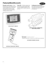
Features/Benefits (cont) Extensive service menu — Unauthorized access to the service menu can be password-protected. Built-in diagnostic capabilities assist in troubleshooting and recommend proper corrective action for pre-set alarms, resulting in greater up time. Alarm file — This file maintains the last 50 time and date-stamped alarm and alert messages in memory. This function reduces troubleshooting time and cost. Configuration data backup — Non-volatile memory provides protection during power failures and eliminates time consuming control reconfiguration. TOUCH PILOT™ DISPLAY SMOOTH ROTARY...
Open the catalog to page 4
Model number nomenclature 30XW Condenser Options - – 2 Pass, NIH, 150 psig (1034 kPa), Victaulic, Discharge Connections (Std) 0 – 2 Pass, NIH, 150 psig (1034 kPa), Victaulic, Suction Connections 1 – 2 Pass, NIH, 150 psig (1034 kPa), Flange, Discharge Connections 2 – 2 Pass, NIH, 150 psig (1034 kPa), Flange, Suction Connections 3 – 2 Pass, NIH, 300 psig (2068 kPa), Victaulic, Discharge Connections 4 – 2 Pass, NIH, 300 psig (2068 kPa), Victaulic, Suction Connections 5 – 2 Pass, NIH, 300 psig (2068 kPa), Flange, Discharge Connections 6 – 2 Pass, NIH, 300 psig (2068 kPa), Flange, Suction Connections...
Open the catalog to page 5
LEGEND AHRI — Air Conditioning, Heating and Refrigeration Institute IPLV — Integrated Part Load Value NOTES: 1. Certified (60 Hz unit) in accordance with AHRI Standard 550/590 at standard rating conditions. 2. Standard rating conditions are as follows: Evaporator Conditions: Leaving Water Temperature: 44 F (6.7 C) Flow: 2.4 gpm per ton (0.043 L/s per kW) Condenser Conditions: Entering Water Temperature:85 F (29.4 C) Flow: 3.0 gpm per ton (0.054 L/s per kW) Fouling Factor (Evaporator): 0.00010 hr x sq ft x F per Btuh (0.000018 m2 x K per W) Fouling Factor (Condenser): 0.00025 hr x sq ft x F per...
Open the catalog to page 6
Physical data 30XW150-400 UNIT PHYSICAL DATA — ENGLISH 30XW UNIT SIZE NOMINAL CAPACITY (tons) UNIT WEIGHT (lb) (Operating/Shipping) COMPRESSORS Compressor Speed (rpm) Compressor Model Number (qty) Unloading Type Minimum Step Capacity % (standard) Minimum Step Capacity % (heat machine) Minimum Step Capacity % (standard with optional mininum load control) Minimum Step Capacity % (heat machine with optional minimum load control) Economizer Temperature Relief Valve Connection (in. SAE Flare) (2 per circuit) REFRIGERANT Charge (lb) Circuit A Charge (lb) Circuit B OIL Charge (gal.) Circuit A Charge...
Open the catalog to page 7
Physical data (cont) 30XW150-400 UNIT PHYSICAL DATA — ENGLISH (cont) 30XW UNIT SIZE NOMINAL CAPACITY (tons) UNIT WEIGHT (lb) (Operating/Shipping) COMPRESSORS Compressor Speed (rpm) Compressor Model Number (qty) Unloading Type Minimum Step Capacity % (standard) Minimum Step Capacity % (heat machine) Minimum Step Capacity % (standard with optional minimum load control) Minimum Step Capacity % (heat machine with optional minimum load control) Economizer Temperature Relief Valve Connection (in. SAE Flare) (2 per circuit) REFRIGERANT Charge (lb) Circuit A Charge (lb) Circuit B OIL Charge (gal.) Circuit...
Open the catalog to page 8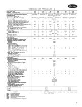
30XW150-400 UNIT PHYSICAL DATA — SI 30XW UNIT SIZE NOMINAL CAPACITY (kW) UNIT WEIGHT (kg) (Operating/Shipping) COMPRESSORS Compressor Speed (r/s) Compressor Model Number (qty) Unloading Type Minimum Step Capacity % (standard) Minimum Step Capacity % (heat machine) Minimum Step Capacity % (standard with optional minimum load control) Minimum Step Capacity % (heat machine with optional minimum load control) Economizer Temperature Relief Valve Connection (in. SAE Flare) (2 per circuit) REFRIGERANT Charge (kg) Circuit A Charge (kg) Circuit B OIL Charge (L) Circuit A Charge (L) Circuit B EVAPORATOR...
Open the catalog to page 9All Carrier| Commercial Systems North America catalogs and technical brochures
 WeatherMaker® 50TCQ
116 Pages
 INFINITY™ 38MPRA
2 Pages
 ActivAIR™ 36CB
24 Pages
 ACTIVAIR™ 36IB
44 Pages
 Axis™
Axis™2 Pages

Archived catalogs
 50ZPB
50ZPB4 Pages
 AHUBuilder
2 Pages
 PERFORMANCE™ 50VT-A
6 Pages
 Carrier® Ductless Systems
8 Pages
 PERFORMANCE™ 50VL-A
6 Pages
 Axis™ Overhead Air Terminals
2 Pages
 ActivAIR™ Induction Beams
2 Pages
 39CC
39CC2 Pages
 A World of Comfort
2 Pages
 Aero® 39M Air Handlers
2 Pages
 17DA Centrifugal Chiller
2 Pages
 Air Handling Units 39 HQ
6 Pages
 48XL-A
30 Pages
 48VL Performance? 14
32 Pages
 48TC WEATHERMAKER®
116 Pages
 48LC WEATHEREXPERT®
52 Pages
 48HC WEATHERMASTER®
124 Pages
 48PM CENTURION?
64 Pages
 48PG CENTURION?
107 Pages
 48A WEATHERMAKER®
116 Pages
 48P WEATHERMASTER®
168 Pages
 48XL Infinity? 15
26 Pages
 OMNIZONE?
80 Pages
 39L AERO®
52 Pages
 30RAP AQUASNAP®
88 Pages
 39S
39S36 Pages
 30RB AQUASNAP®
92 Pages
 EVERGREEN® 23XRV
32 Pages
 AQUAFORCE® 30XA
150 Pages
 EVERGREEN® 30HXA,HXC076-271
52 Pages
 16TJ
16TJ32 Pages
 AQUASNAP® 30MPA,MPW015-045
36 Pages
 39M AERO®
110 Pages
 19XR EVERGREEN®
56 Pages
 Aero Air-Handling Units
2 Pages


- Medical sensor
- Temperature sensor
- Digital thermoregulator
- Cooling thermostat
- Heating thermostat
- Humidity sensor
- Cleanroom air handling unit
- Air-cooled water chiller
- Modular air handling unit
- Thermostat with touchscreen
- Water-cooled water chiller
- Ceiling-mounted fan coil unit
- Wall-mounted fan coil unit
- Floor-mounted fan coil unit
- Air/air heat pump
- Geothermal heat pump