- Catalogs
- Citizen Chiba Precision
- BSD-36 Series
BSD-36 Series
1 /2Pages
BSD-36 Series
1 /2Pages
Catalog excerpts
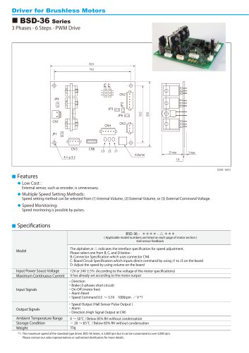
Driver for Brushless Motors 3 Phases - 6 Steps - PWM Drive Multiple Speed Setting Methods: Speed Monitoring: External sensor, such as encoder, is unnecessary. Speed setting method can be selected from (1) Internal Volume, (2) External Volume, or (3) External Command Voltage. Speed monitoring is possible by pulses. ( Applicable model numbers are listed on each page of motor section ) Hall sensor feedback Input Power Souce Voltage Maximum Continuous Current The alphabet at △ indicates the interface specification for speed adjustment. Please select one from B, C, and D below : B: Connector Specification which uses connector CN4 C: Board Circuit Specification which inputs direct command by using J1 to J3 on the board D: Adjust the speed by using volume on the board 12V or 24V ±5% (According to the voltage of the motor specifications) It has already set according to the motor output Input Signals ・Direction ・Brake (3-phases short circuit) ・On-Off (motor free) ・Alarm Reset ・Speed Command 0.5 ∼ 5.5V 1000rpm / V *1 Output Signals ・Speed Output (Hall Sensor Pulse Output ) ・Alarm ・Direction (High Signal Output at CW) Ambient Temperature Range Storage Condition Weight 0 ∼ 50℃ / Below 85% RH without condensation − 20 ∼ 85℃ / Below 85% RH without condensation 55g *1 : The maximum speed of the standard type driver, BSD-36 Series, is 5,000 rpm but it can be customized to over 5,000 rpm. Please
Open the catalog to page 1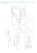
Input to Reset Alarm Start Input Brake Input Command Input for Rotating Direction *Power voltage is output only when JP4 is short - circuited Vref Voltage for Speed Setting (0.5 5.5V) Pads are prepared for direct soldering on board Gain Settings Power Circuit Vref (Output from Motor Drive IC) +12V Output for Rotating Direction Fault Output Pulse Output Coil for Brushless Motor Hall Sensor for Brushless Motor
Open the catalog to page 2All Citizen Chiba Precision catalogs and technical brochures
 Galvanometer Optical Scanner
24 Pages
 Coreless DC Motors
36 Pages
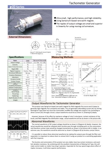 23 Series
1 Page
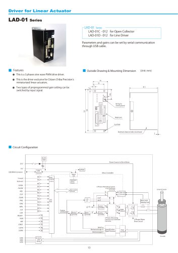 LAD-01 Series
2 Pages
 TSD-04-060
2 Pages
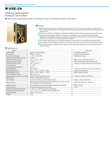 USE-2A
2 Pages
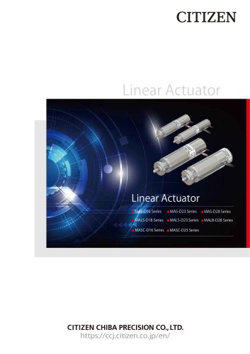 Linear Actuator
20 Pages
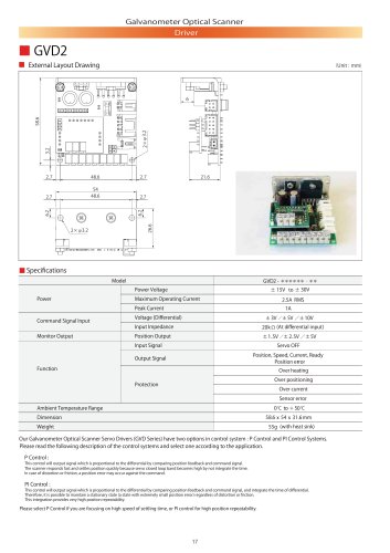 GVD2
GVD22 Pages
 GVD1
GVD12 Pages
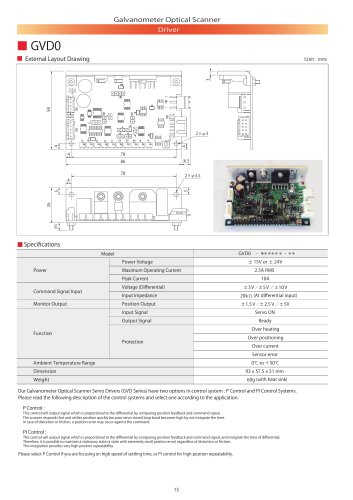 GVD0
GVD02 Pages
 Minituarized AC Servomotors
16 Pages

- Microscopy
- Compound microscope
- Laboratory microscope
- Medical sensor
- Temperature sensor
- Dental milling machine
- Actuator
- Linear actuator
- Face-cover shield
- CAD/CAM milling machine
- Electric actuator
- Medical actuator
- Medical industry motor
- Ceramic milling machine
- Humidity sensor
- Medical face-shield
- 3D microscope
- Laser module