
- Catalogs
- Citizen Chiba Precision
- Coreless DC Motors

Coreless DC Motors
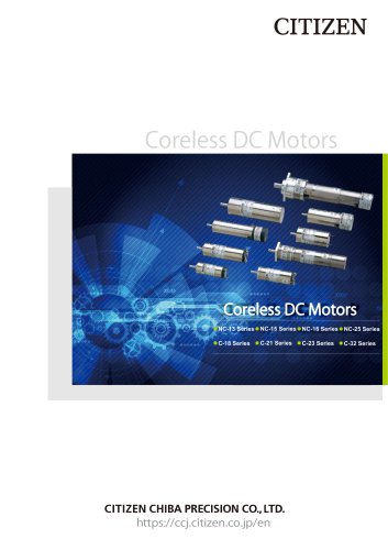
Coreless DC Motors
- The document provides detailed specifications and features of various series of coreless DC motors, including NC and C series.
- It includes information on planetary gearheads and control drivers for speed, torque, and position control.
Features
- Coreless DC motors are designed for high response and power, utilizing rare earth magnets and strong coils.
- NC-Series motors achieve higher power than C-Series by using neodymium boron magnets.
- Options available include planetary gearheads, encoders, tachometer generators, and drivers for enhanced control and performance.
- Motors offer smooth rotation with low vibration and noise, high-speed rotation, and high output per unit volume.
Specifications
- Specifications are provided for different models, including rated voltage, maximum output, continuous current, torque, speed, and more.
- Details on motor configurations, including diameter, length, and design numbers, are included.
Basic Characteristics
- Characteristics of DC servomotors are represented by T-N and T-I curves, showing linear relationships due to high-performance magnets.
- Compensated voltage control is the most common method for controlling these motors.
Model Number and Unit Conversion
- Includes a conversion chart for torque, rotor inertia, weight, length, and speed.
- Model numbers are explained with details on configuration, gearhead type, and encoder specifications.
Special Features
- Motors are available with tachometer generators and optical encoders for precise control.
- Encoders are compact and cost-effective, with options for different response frequencies.
Cautions for Handling
- Guidelines for handling and operating the motors are provided to ensure optimal performance and longevity.
Catalog excerpts

Series ● NC-15 Series ● NC-18 Series ● NC-25 Series
Open the catalog to page 1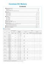
Coreless DC Motors Contents ■ General Information ● Features ● Basic Characteristics ● Model Number ・Unit Conversion Chart ■ NC Series ● NC-13 Series ● NC-15 Series ● NC-18 Series ● NC-25 Series ■ C Series ● C-18 Series ● C-21 Series ● C-23 Series ● C-32 Series ■ Control Drivers ● USE-2A for Speed, Torque, and Voltage Control ● TSD-04-060 for Position Control ■ Models for Special Environments ■ Coreless DC Motors Motor Specifications Size Series Specification (Rated) Voltage V Tachometer Generator *1 : The diameter of the motor alone is φ17mm and the one with encoder or tachometer generator...
Open the catalog to page 2
■ Our Miniaturized Coreless DC Servomotor Series achieved high response and high power by adapting powerful rare earth magnets and mechanically-strong coils. And also, NC-Series achived higher power than C-Series by using neodymium boron magnets with high flux density. By considering the actual usability, many options are availble according to your applications. By combining these options such as planetary gearhead, encoder, tachometer generator, and driver, you can further improve control of the reliability, accuracy, and performance. Because the mechanical time constant is small for rotor inertia...
Open the catalog to page 3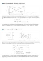
■ Basic Characteristic of DC Servomotor (at Rated Voltage) No Load Point Starting Point No:No Load Speed (rpm) In general, the characteristic of a DC motor can be represented by T-N and T-I Curves. In the case of moving coil type DC motors with high performance rare earth magnets, these two curves become perfectly linear for the armature reaction can be completely ignored. IS − IO I = IO + ・T(A) (1) TS NO N = N O − ・T(rpm) (2) TS From above formula, the current and speed can be calculated when rated voltage is applied to the motor and used by loaded torque (mN・m)....
Open the catalog to page 4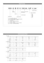
Model Number Outer Diameter Number of Encoder Pulses and Channels With Gearhead Design Number NC :Motor (Nd magnet) only TNC :Motor (Nd magnet) + Tachometer Generator ENC :Motor (Nd magnet) + Encoder C :Motor only TC :Motor + Tachometer Generator EC :Motor + Encoder ETC :Motor + Tachometer Generator + Encoder LEC :Motor + Cost-Effective Encoder Unit Conversion Chart ● Rotor Inertia
Open the catalog to page 5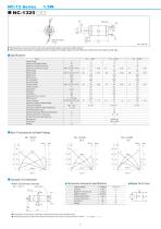
Motor Lead The positions of screw holes and motor lead (terminals) cannot be determined. ● When positive electrode is applied to the red lead, the shaft rotates to CW direction seen from the output shaft side. ● ■ Specifications Items Rated Voltage Maximum Allowable Output Maximum Continuous Current Maximum Continuous Torque Rated Output Rated Torque Rated Speed Rated Current No Load Speed No Load Current Starting Torque Starting Current Rotor Inertia Resistance Inductance Mechanical Time Constant EMF Constant Torque Constant Maximum Output at Rated Voltage Starting Acceleration Housing-to Ambient...
Open the catalog to page 6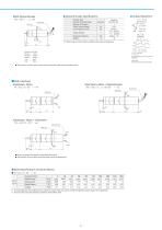
■ Optical Encoder Specifications Optical Encoder Encoder Type Number of Output Pulses Number of Channels Power Source Voltage Consumption Current Encoder Cable Motor Lead Response Frequency Weight Output Timing ( CW dorectoion seen from the output shaft side ) The positions of screw holes, motor lead, and encoder cable cannot be determined. Gearhead + Motor + Optical Encoder Encoder Cable Motor Lead Motor Lead Gearhead + Motor + Tachometer Tachometer Lead Motor Lead Blue Please see page 23 for details on gearhead dimensions. The positions of screw holes and motor lead cannot be determined. ■ Rated...
Open the catalog to page 7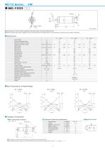
Motor Lead The positions of screw holes and lead wires (terminals) cannot be determined. ● When positive electrode is applied to the red lead wire, the shaft rotates to CW direction seen from the output shaft side. ● ■ Specifications Rated Voltage V W mA mN・m gf・cm oz・in W mN・m gf・cm oz・in rpm mA rpm mA mN・m gf・cm oz・in A g ・cm 2 Ω mH m-sec V / 10 3 rpm mN ・m/A gf・cm/A oz・in/A W rad / sec 2 ℃/ W − ℃ ℃ − − − g Maximum Allowable Output Maximum Continuous Current Maximum Continuous Torque Rated Output Rated Torque Rated Speed Rated Current No Load Speed No Load Current Starting Torque Starting Current...
Open the catalog to page 8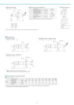
Optical Encoder ■ Optical Encoder Specifications Encoder Type Number of Output Pulses Number of Channels Power Source Voltage Consumption Current Encoder cable Motor Lead Response Frequency Weight Output Timing ( CW direction seen from the output shaft side ) The positions of screw holes, motor lead, and encoder cable cable cannot be determined. Gearhead + Motor NC −1333 □□G ZCP 1 / xxx ● Gearhead + Motor + Optical Encoder Encoder cable Motor Lead Motor Lead Gearhead + Motor + Tachometer Tachometer Lead Motor Lead Blue Please see page 23 for details on gearhead dimensions. The positions of screw...
Open the catalog to page 9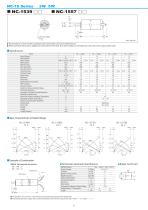
The positions of screw holes and lead wires (terminals) cannot be determined. ● When positive electrode is applied to the positive terminal, the shaft rotates to CW direction seen from the output shaft side. ● Items Rated Voltage Rated Output Rated Torque Rated Speed Rated Current No Load Speed No Load Current Starting Torque Starting Current Rotor Inertia Resistance Inductance Mechanical Time Constant EMF Constant Torque Constant Maximum Output at Rated Voltage Starting Acceleration Housing-to Ambient Thermal Resistance Winding Insulation Class Maximum Armature Winding Temperature Operating...
Open the catalog to page 10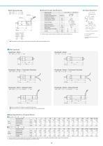
■ Optical Encoder Specifications Optical Encoder ENC −1539 □□ △△△ /3ch ENC −1557 □□ △△△ /3ch Encoder Cable Motor Lead Encoder Lead Color Phase A …… Green Phase B …… Yellow Phase Z …… White + 5V ……… Red GND ……… Black ● Rectangular Wave ( CW direction seen from the output shaft side ) t 1 +t 2 ,t 3 +t 4 =T/2±T/8 t 1 ,t 2 ,t 3 ,t 4 ≧T/8 T 0 =T±T/2 The position of Phase A, B and Z cannot be determined. The positions of screw holes, motor lead, and encoder cable cannot be determined. Gearhead + Motor + Optical Encoder Gearhead + Motor + Optical Encoder Gearhead + Motor + Tachometer Generator Gearhead...
Open the catalog to page 11All Citizen Chiba Precision catalogs and technical brochures
 Galvanometer Optical Scanner
24 Pages
 23 Series
1 Page
 LAD-01 Series
2 Pages
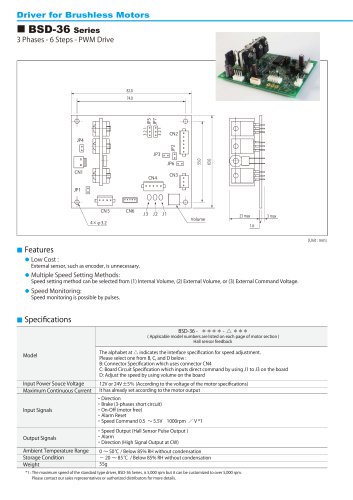 BSD-36 Series
2 Pages
 TSD-04-060
2 Pages
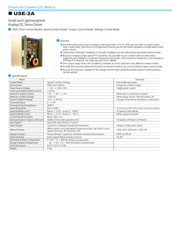 USE-2A
2 Pages
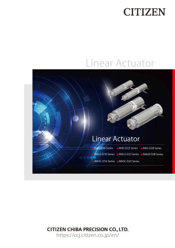 Linear Actuator
20 Pages
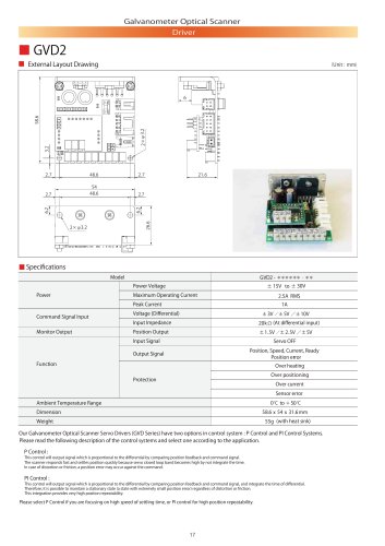 GVD2
GVD22 Pages
 GVD1
GVD12 Pages
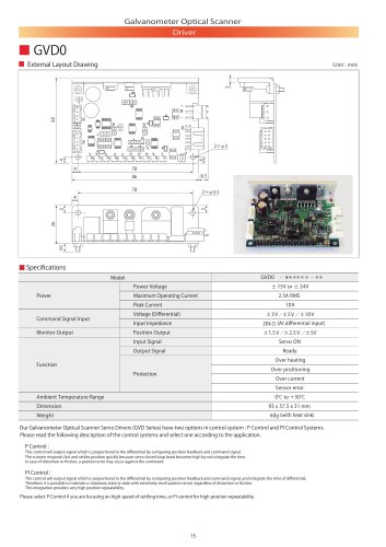 GVD0
GVD02 Pages
 Minituarized AC Servomotors
16 Pages

- Microscopy
- Compound microscope
- Laboratory microscope
- Medical sensor
- Temperature sensor
- Actuator
- Linear actuator
- Dental milling machine
- CAD/CAM milling machine
- Face-cover shield
- Electric actuator
- Medical industry motor
- Medical actuator
- Brushless motor
- Ceramic milling machine
- Humidity sensor
- Medical face-shield
- 3D microscope
- Confocal microscope