- Catalogs
- Citizen Chiba Precision
- Galvanometer Optical Scanner
Galvanometer Optical Scanner
1 /24Pages

Galvanometer Optical Scanner
1 /24Pages
Catalog excerpts

Galvanometer Optical Scanner Galvanometer Optical Scanner ● GVM-0930S ● GVM-2260
Open the catalog to page 1
Galvanometer Optical Scanner & Driver ■ Galvanometer Optical Scanner (also called as galvo scanner / galvano motor / galvanometer mirror scanner) is the motor with high precision position sensor which detects position to adjust the scan angle of the mirror reflecting laser beam. It has a variety of applications in combination with laser beam, such as laser marker, confocal microscopes, and LiDAR. Fast response / Low inertia / High torque ● High linearity and positioning accuracy ● Superior temperature characteristics and minimal humidity effect Laser marking Laser microscope ● Image capturing ●...
Open the catalog to page 2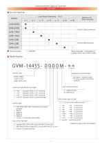
Galvanometer Optical Scanner Scanner ■ Scanner Selection Laser Beam Diameter φ3 Method to Fix *Mirror Assembly Fixed to shaft by adhesive Fixed to shaft by screws *Mirror Assembly : combination of a galvano mirror and a mirror holder Registered Custom Number *It is only used for customized products With or Without Mirror Scanning Angle (Mechanical Angle) 0:±10° 1:±15° 2:±20° C :Custom 0 :Without mirror M:With mirror Bumpers set for ±10°scanning Bumpers set for ±15°scanning Bumpers set for ±20°scanning Bumpers set for customized angle Mirror Angle Against Cable 0:0°(It is also 0 when without...
Open the catalog to page 3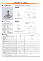
Galvanometer Optical Scanner Scanner ■ This drawing indicates the combination of GM7 mirror assembly Spot Center Reflective Surface Maximum Scan Angle (Mechanical Angle) Rotor Inertia Spot Center Dedicated connection cable is required. ( Please see page10 for more details ) SHIELD SHIELD − MOTOR WINDING + MOTOR WINDING Dedicated connection cable is required. ( Please see page10 for more details ) Coil Resistance Coil Inductance Torque Constant Back EMF Voltage Peak Current Maximum Coil Temperature Weight Gain Drift Output Signal Input Signal Common Mode Differential Mode Offset Drift Step Response...
Open the catalog to page 4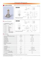
■ This drawing indicates the combination of GM7 mirror assembly Spot Center Galvanometer Optical Scanner Scanner Reflective Surface SHIELD SHIELD − MOTOR WINDING + MOTOR WINDING Spot Center Dedicated connection cable is required. ( Please see page10 for more details ) Reflective Surface ● Dedicated connection cable is required. ( Please see page10 for more details ) ■ Specifications Items Maximum Scan Angle (Mechanical Angle) Rotor Inertia Coil Resistance Torque Constant Peak Current Maximum Coil Temperature Weight Repeatability Offset Drift Gain Drift Step Response Time Input Signal Coil Inductance...
Open the catalog to page 5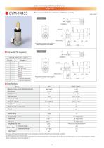
■ This drawing indicates the combination of GM0 mirror assembly Spot Center Galvanometer Optical Scanner Scanner Reflective Surface connection cable is required. ( Please see page10 for more details ) Maximum Scan Angle (Mechanical Angle) Rotor Inertia 8.2 Reflective Surface ● Dedicated connection cable is required. ( Please see page10 for more details ) Spot Center A B PD COM AGC RETURN AGC IN SHIELD SHIELD SHIELD − MOTOR WINDING + MOTOR WINDING Coil Resistance Coil Inductane Torque Constant Peak Current Maximum Coil Temperature Weight Repeatability Non-Linearity (± 10 °) Gain Drift 0.1 (Maximum)...
Open the catalog to page 6
Galvanometer Optical Scanner Scanner ■ This drawing indicates the combination of GM1 mirror assembly Spot Center Reflective Surface ● Dedicated connection cable is required. ( Please see page10 for more details ) Spot Center A B PD COM AGC RETURN AGC IN SHIELD SHIELD SHIELD − MOTOR WINDING + MOTOR WINDING Dedicated connection cable is required. ( Please see page10 for more details ) ■ Specifications Items Maximum Scan Angle (Mechanical Angle) Rotor Inertia Coil Resistance Coil Inductance Torque Constant Peak Current Maximum Coil Temperature Weight Repeatability Offset Drift Gain Drift Step Response...
Open the catalog to page 7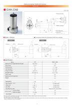
Galvanometer Optical Scanner Scanner (Unit:mm) ①Sensor Connector ②Motor Connector Made by HIROSE ELECTRIC CO.,LTD. ■ This drawing indicates the combination of GM2 mirror assembly Reflective Surface Spot Center Reflective Surface Spot Center Maximum Scan Angle (Mechanical Angle) Rotor Inertia Coil Resistance Torque Constant Maximum Coil Temperature Weight Non-Linearity (± 10 °) Gain Drift Step Response Time Input Signal Offset Drift Output Signal Coil Inductance Peak Current Common Mode Differential Mode *Please see the caution below * The values of the specification are based on the combination...
Open the catalog to page 8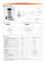
Galvanometer Optical Scanner Scanner (Unit:mm) ①Sensor Connector ②Motor Connector Made by HIROSE ELECTRIC CO.,LTD. ■ This drawing indicates the combination of GM4 mirror assembly Reflective Surface Spot Center Reflective Surface Spot Center ■ Specifications Specifications Items Maximum Scan Angle (Mechanical Angle) Rotor Inertia Coil Resistance Coil Inductance Torque Constant Back EMF Voltage Peak Current Weight Common Mode Differential Mode Step Response Time Offset Drift Gain Drift Input Signal Maximum Coil Temperature Output Signal *Please see the caution below * The values of the specification are...
Open the catalog to page 9
Galvanometer Optical Scanner Scanner (Unit:mm) ①Sensor Connector Made by HIROSE ELECTRIC CO.,LTD. ■ This drawing indicates the combination of GM5 mirror assembly X -Axis Spot Center ②Motor Connector Spot Center Reflective Surface Reflective Surface Maximum Scan Angle (Mechanical Angle) Rotor Inertia Coil Resistance Coil Inductance Torque Constant Peak Current Maximum Coil Temperature Weight Repeatability Non-Linearity (± 10 °) Gain Drift 0.1 (Maximum) 10 (Maximum) 50 (Maximum) Step Response Time Input Signal Offset Drift Output Signal Common Mode Differential Mode *Please see the caution below *...
Open the catalog to page 10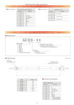
Galvanometer Optical Scanner GVM-2260/ GVM-2280/ GVM-2510 / Connector Pin Sequence ■Sensor Connector ■Motor Connector Frame Ground GVM-0930/ GVM-1445 / Dedicated Connection Cable ■ Model Number Cable Length Registered Custom Number No Number : Standard Product *It is only used for customized products
Open the catalog to page 11
Galvanometer Optical Scanner Mirror Mirror Substrate : Si (Silicon) Laser Beam Diameter Mirror Model Fixed to shaft by adhesive Fixed to shaft by screws Mirror Assembly Inertia (g・cm² ) ※ If combining GVM-1445L with φ10 mirror, the mirror holder will be fixed to the shaft by adhesive. G M 0 X 0 0 - ** Registered Custom Number Laser Beam Diameter Mirror Shape X:X or first mirror Y :Y or second mirror C :Customized mirror No Number Standard Product : *It is only used for customized products Substrate of Coating 0: Au (Gold) coating (10.6μm)
Open the catalog to page 12All Citizen Chiba Precision catalogs and technical brochures
 Coreless DC Motors
36 Pages
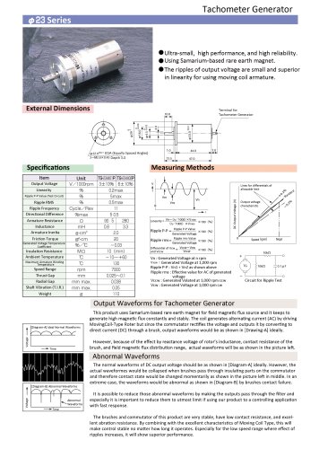 23 Series
1 Page
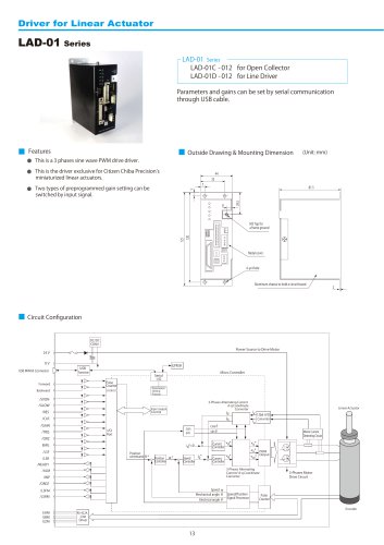 LAD-01 Series
2 Pages
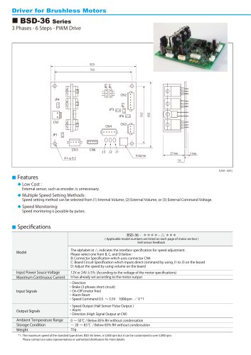 BSD-36 Series
2 Pages
 TSD-04-060
2 Pages
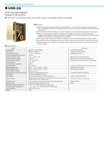 USE-2A
2 Pages
 Linear Actuator
20 Pages
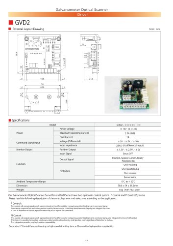 GVD2
GVD22 Pages
 GVD1
GVD12 Pages
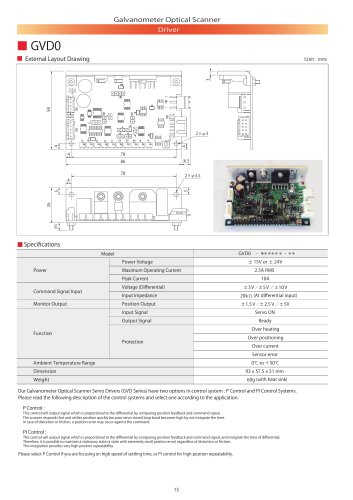 GVD0
GVD02 Pages
 Minituarized AC Servomotors
16 Pages

- Compound microscope
- Laboratory microscope
- Medical sensor
- Temperature sensor
- Dental milling machine
- Actuator
- Linear actuator
- Face-cover shield
- CAD/CAM milling machine
- Electric actuator
- Medical actuator
- Medical industry motor
- Brushless motor
- Ceramic milling machine
- Humidity sensor
- Medical face-shield
- 3D microscope
- Laser module