GVD2
1 /2Pages
GVD2
1 /2Pages
Catalog excerpts

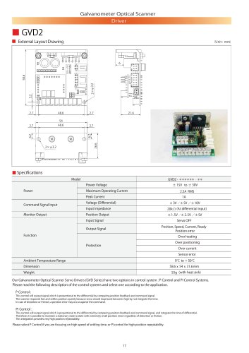
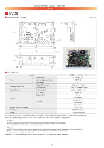
Galvanometer Optical Scanner Driver ■ External Layout Drawing ■ Specifications Model Power Power Voltage Maximum Operating Current Peak Current Command Signal Input Monitor Output Voltage (Differential) Input Impedance Position Output Input Signal Servo OFF Position, Speed, Current, Ready Position error r Output Signal Function Over heating Over positioning Over current Sensor error 0 ℃ to + 50 ℃ Ambient Temperature Range 55g (with heat sink) Our Galvanometer Optical Scanner Servo Drivers (GVD Series) have two options in control system : P Control and PI Control Systems. Please read the following description of the control systems and select one according to the application. P Control : This control will output signal which is proportional to the differential by comparing position feedback and command signal. The scanner responds fast and settles position quickly because servo closed loop band becomes high by not integrate the time. In case of distortion or friction, a position error may occur against the command. This control will output signal which is proportional to the differential by comparing position feedback and command signal, and integrate the time of differential. Therefore, it is possible to maintain a stationary state (a state with extremely small position error) regardless of distortion or friction. This integration provides very high position repeatability. Please select P Control if you are focusing on high speed of s
Open the catalog to page 1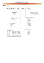
Galvanometer Optical Scanner Driver ■ Model Number Registered Custom Number No Number : Standard Product *It is only used for customized products Beam Diameter (Mirror size) Control System Command Voltage Mechanical Angle Bumpers set for ±10 °scanning 0:±10 ° Bumpers set for ±5°scanning 1:±5° Bumpers set for ±7.5 °scanning 2:±7.5 ° 3:±12.5 ° Bumpers set for ±12.5 °scanning Bumpers set for ±15 °scanning 4:±15
Open the catalog to page 2All Citizen Chiba Precision catalogs and technical brochures
 Galvanometer Optical Scanner
24 Pages
 Coreless DC Motors
36 Pages
 23 Series
1 Page
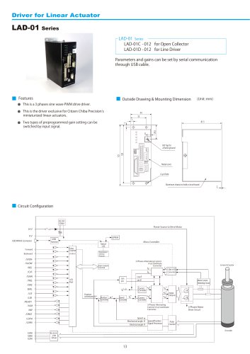 LAD-01 Series
2 Pages
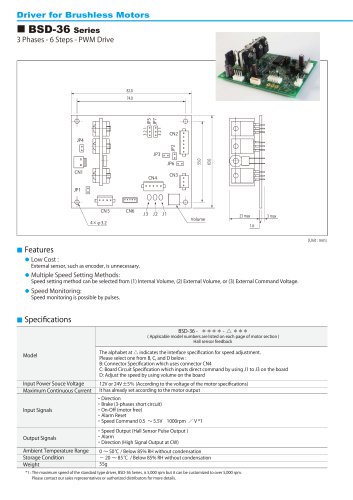 BSD-36 Series
2 Pages
 TSD-04-060
2 Pages
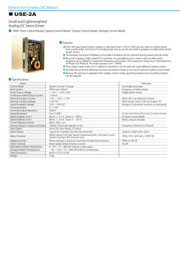 USE-2A
2 Pages
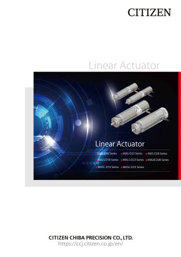 Linear Actuator
20 Pages
 GVD1
GVD12 Pages
 GVD0
GVD02 Pages
 Minituarized AC Servomotors
16 Pages

- Microscopy
- Compound microscope
- Laboratory microscope
- Medical sensor
- Temperature sensor
- Dental milling machine
- Actuator
- Linear actuator
- Face-cover shield
- CAD/CAM milling machine
- Electric actuator
- Motor
- Medical actuator
- Medical industry motor
- Brushless motor
- Ceramic milling machine
- Humidity sensor
- Medical face-shield
- 3D microscope
- Laser module