- Catalogs
- Citizen Chiba Precision
- TSD-04-060
TSD-04-060
1 /2Pages

TSD-04-060
1 /2Pages
Catalog excerpts
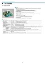
Drivers for Coreless DC Motors ● Because it is a full software servo, it would not be affected by the environment such as temperature. ● Synchronous Tracking Drive Circuit : It is possible to control with almost no accumulated error pulse (pulse pool). Since it is integrated, stable and high-precision positioning is possible. ● Single Power Source : Because it supplies only a single DC power source, a commercially available switching regulator battery can be used. ● Multiplication Function in Encoder ×1, ×2, ×4 multiplications are selectable by internal setting. Several Protection Circuits are installed to protect the motor. Input Power Source Rated Output Maximum Output Output System Feedback Operating Ambient Temperature Storage Condition Input Signal Output Signal Multiplication Safeguard Function Adjustment Display Check Terminal Structure Outside Dimensions Weight DC12V ∼ 40V *Please apply it according to the motor specification Driver Output 120W (When the power source voltage is 40V) Driver Output 240W (When the power source voltage is 40V) Full Bridge PWM System 3 Phases (A/ B/ Z), Incremental Encoder, Line Driver or Open Collector Below 85% RH without condensation 0℃∼ 40℃ − 20℃∼ 85℃ Below 85% RH without condensation Position Control (*Please serelet one: CW/ CCW, Pulse/ DIR, 2 Phase Input), Counter Clear, Reset, External Alarm Input, Gain Low Input Alarm Output, Deviation Counter Overflow, Ready, In Position, Encoder Output A/ B/ Z (Line Driver Output) Encoder Multiplication ×1, ×2, ×4 (set by DIP Switch) Deviation Counter Overflow, Driver Overheat, Detection of Full Torque and Overrun Gain Adjustment, Speed Loop Gain, Speed Loop Integral TC, Speed Feedback Gain, Derivative Gain, Positioning Gain OF (Deviation Counter Overflow), RDY (Ready), IP (In Position), ALM (Alarm), PWR (Inte rnal Power Confirmation) SPD: Motor Speed Waveform, TRQ: Motor Current Waveform Open Frame H40×L120 ×W102
Open the catalog to page 1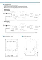
■ Operating Block Diagrams The diagrams below are operating block diagrams of the driver. Although it is not shown in the diagrams, the external input / output parts are isolated by a photocoupler. However, the encoder output is not isolated and so it is a line driver output. After removing noise, the external input will be transformed into waveform and then input to the controller. Pulse Pool Mode Integral Time Constant Command Pulse Current Control Proportional Gain Speed Loop Speed Feedback Current Feedback Derivative Time Constant Synchronous Tracking Mode ∫dt Command Pulse VR 3 Integral...
Open the catalog to page 2All Citizen Chiba Precision catalogs and technical brochures
 Galvanometer Optical Scanner
24 Pages
 Coreless DC Motors
36 Pages
 23 Series
1 Page
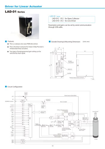 LAD-01 Series
2 Pages
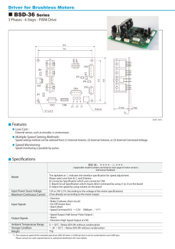 BSD-36 Series
2 Pages
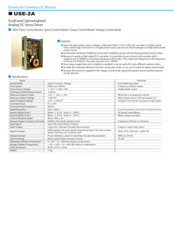 USE-2A
2 Pages
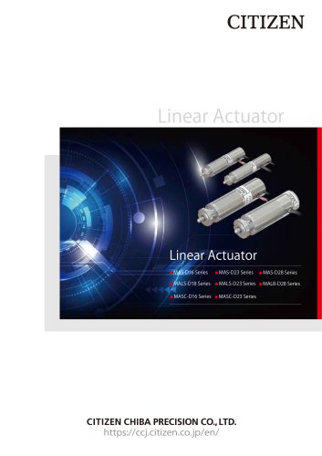 Linear Actuator
20 Pages
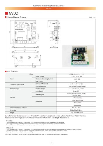 GVD2
GVD22 Pages
 GVD1
GVD12 Pages
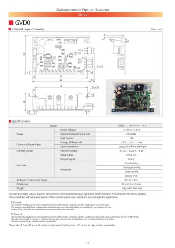 GVD0
GVD02 Pages
 Minituarized AC Servomotors
16 Pages

- Microscopy
- Compound microscope
- Laboratory microscope
- Medical sensor
- Temperature sensor
- Dental milling machine
- Actuator
- Linear actuator
- Face-cover shield
- CAD/CAM milling machine
- Electric actuator
- Medical actuator
- Medical industry motor
- Brushless motor
- Ceramic milling machine
- Humidity sensor
- Medical face-shield
- 3D microscope
- Laser module