- Catalogs
- Clover Next
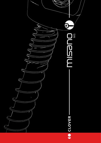
- MISANO (MIS)
MISANO (MIS)
1 /16Pages
MISANO (MIS)
1 /16Pages
Catalog excerpts
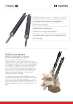
Complete set of sizes for open, mis and deformity procedures Self-tapping screw for insertion even without tapping Great mechanical properties Double thread for improved sealing Sophisticated yet compact instrumentation Cannulated screw for injection of cement or bone substitute Sterile packaging Stabilization system thoracolumbar vertebral Misano is the first stabilization system thoracolumbosacral, totally made of titanium, which allows the use of a single pedicle screw for the treatment of all degenerative, traumatic, and deformity pathologies. The self-tapping screw can be inserted without...
Open the catalog to page 2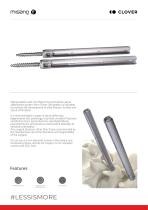
Appropriately used, the Misano thoracolumbar-sacral stabilization system from Clover Orthopedics is indicated to promote the development of solid thoracic, lumbar and sacral arthrodesis. It is recommended in cases of spinal deformity, degenerative disc pathology, traumatic vertebral fractures, vertebral tumors, spinal stenosis, spondylolisthesis, pseudoarthrosis, and previous unsuccessful attempts at vertebral arthrodesis. Any surgical decisions other than those recommended by the manufacturer are at the discretion and responsibility of the surgeon. Do not use 4.5 mm diameter screws in the lumbar...
Open the catalog to page 3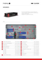
Clover has invested heavily in instrument design and care with the goal of creating ergonomic, functional, and compact instrumentation. Designed for the surgeon and his team. 1 CEMENT NEEDLE ADAPTER 2 DUAL LEAD CAP SCREWDRIVER 5 GUIDE WIRE TROCAR 7 COUNTER TORQUE HANDLE
Open the catalog to page 4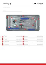
MSN-F0SS00000S 28 DUAL LEAD MIS SCREWDRIVER
Open the catalog to page 5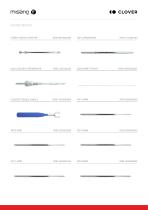
CEMENT NEEDLE ADAPTER DUAL LEAD MIS SCREWDRIVER GUIDE WIRE TROCAR COUNTER TORQUE HANDLE
Open the catalog to page 6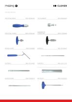
RATCHETING HANDLE TULIP ALIGNMENT
Open the catalog to page 7
SLIDING RING
Open the catalog to page 8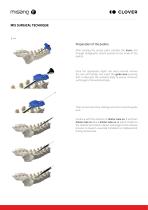
1— Preparation of the pedicle After locating the access point, position the trocar and through radiographic control proceed to the inside of the pedicle. Once the appropriate depth has been reached remove the core and handle, and insert the guide wire ensuring that it intercepts the vertebral body to ensure minimum anchorage to the vertebral body. Then remove the trocar making sure not to move the guide wire. Continue with the insertion of dilator tube no. 1 and then dilator tube no. 2 and dilator tube no. 3, which, thanks to the toothed termination allows anchorage to the articular process to...
Open the catalog to page 10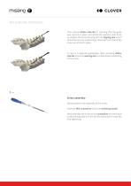
MIS SURGICAL TECHNIQUE Then remove dilator tube No. 1, checking that the guide wire remains in place, and should the operator wish to do so, prepare the screw housing with the tapping tool, which should be one size undersized in diameter from that of the screw you intend to place. In case it is deemed appropriate, after removing dilator tube No. 2 use the reaming awl to enable better positioning of the screw. 2— Screw assembly Next proceed to the assembly of the screw. Hook the MIS screwdriver onto the ratcheting handle. Next assemble the screw to the screwdriver by inserting it inside the tulip...
Open the catalog to page 11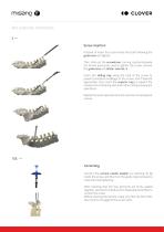
MIS SURGICAL TECHNIQUE 3— Screw insertion Proceed to insert the screw inside the stalk following the guide wire and tighten. Then slide out the screwdriver, turning counterclockwise the ferrule previously used to tighten the screw, remove the guide wire and dilator tube No. 3. Insert the sliding ring along the tulip of the screw to prevent premature breakage of the screw, and if deemed appropriate, also insert the superior ring to prevent the screws from interfering with each other during subsequent operations. Repeat the same operations for the insertion of subsequent screws. Opt. — Cementing...
Open the catalog to page 12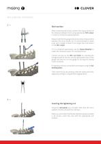
Rod insertion After positioning the screws, perform the measurement of the distance between them using appropriate MIS caliper in order to choose the appropriate bar. Please note that the gauge shows the actual measurement between the screw heads, so it is recommended to insert a bar with a length at least 5 mm longer than that shown on the MIS caliper. If it is considered appropriate, use the tissue dissector to create the necessary space for inserting the bar. Connect the bar to the MIS rod holder by inserting the hexagonal part of the bar into the appropriate hole on the gauge and secure it...
Open the catalog to page 13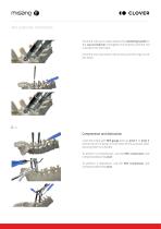
Once the nuts are in place, attach the ratcheting handle to the cap screwdriver and tighten the locknuts until the rod is pushed into the tulips. Once the rod is secured to the screws, pull the rings out of the tulips. 6— Compression and distraction Cover the tulips with MIS gauge and use pivot 1 or pivot 2 as the fulcrum of action in the center of the cannulas-after securing them to a handle. To perform a compression, use the MIS compressor and compress below the pivot. To perform a distraction, use the MIS compressor and compress above the pivot.
Open the catalog to page 14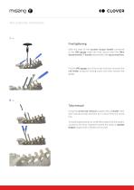
7— Final tightening With the help of the counter torque handle connected to the MIS gauge make the final closure with the 9Nm dynamometric T-handle assembled to the cap screwdriver. Pull the MIS gauge out of the tulips and then unscrew the rod holder using the locking crown and then remove the gauge. 8— Tulip removal Using the screw tab removal coupled with a handle, hook each individual tulip and then pry it loose from the screw cup. To avoid displacements or small deformations of the system caused by the force required to break the tulips, a counter torque coupled with a handle can be used
Open the catalog to page 15
MONOAXIAL SCREW CANNULATED - FENESTRATED POLIAXIAL SCREW CANNULATED - FENESTRATED TITANIUM PRECURVED ROD TITANIUM ROD CO-CR ROD CLAMPING CAP FOR SCREWS AND HOOKS DOMINOES LONGITUDINAL CONNECTION ELEMENT MODULAR CROSSLINK ANGLED OFFSET OFFSET LUMBAR WIDE HOOK PEDICLE HOOK TORACHIC LAMINAR HOOK OLBIQUE HOOK - DX/SX OFFSET HOOK - DX/SX LUMBAR NARROW HOOK FROM L30 TO L55 FROM L30 TO L55 FROM L30 TO L55 FROM L30 TO L55 FROM L25 TO L40 FROM L30 TO L55 FROM L30 TO L55 FROM L30 TO L90 FROM L30 TO L90 FROM L45 TO L90 S - M - L - XL FROM L20 TO L60 FROM L20 TO L60 FROM SIZE 7 TO SIZE 11 FROM SIZE 5 TO...
Open the catalog to page 16All Clover Next catalogs and technical brochures
 MONOCYTES-R
5 Pages
 EVO
EVO9 Pages
 MISANO (OPEN)
17 Pages
 MONZA LUMBAR PLIF TLIF
14 Pages
 MONZA CERVICAL
9 Pages
 LIPOCELL™
6 Pages
 MONZA LLIF
4 Pages
 CERVICAL PEEK
7 Pages
 RALLY
RALLY4 Pages
 DIXI
DIXI4 Pages
- Interbody fusion cage
- Metal burr
- PEEK interbody fusion cage
- Collection kit
- Anterior interbody fusion cage
- Lumbar interbody fusion cage
- Spinal stabilization system
- Cervical interbody fusion cage
- Adult spinal osteosynthesis unit
- Titanium interbody fusion cage
- Posterior interbody fusion cage
- Transforaminal interbody fusion cage
- Surgical bur
- Straight burr
- Conical bur
- Shoulder prosthesis
- Lateral interbody fusion cage
- Titanium burr
- Orthopedic surgery burr
- 3D-printed interbody fusion cage