


Adobe PDFPoolpod 3.0 Setting out
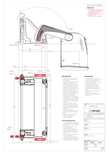
Adobe PDFPoolpod 3.0 Setting out
- All loading drawings must be read alongside relevant load calculations, considering appropriate local factors.
- All dimensions and settings must be confirmed on site.
- Refer to the architectural drawing for additional notes.
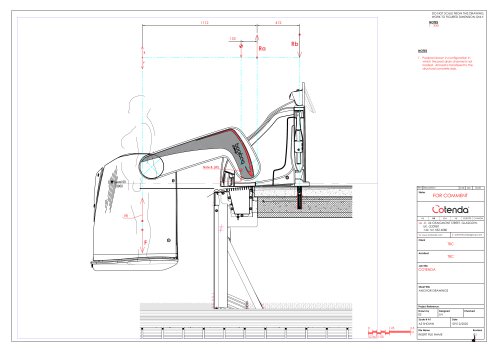
- The telescopic rear foot distributes downward pressure over a designated area.
- Upward loads, when the platform is over the pool, are transferred via black circular anchor sockets on each side.
- The standard telescopic adapter positions the anchor hole between 760mm and 885mm from the pool edge, while the extra-long adapter positions it between 890mm and 1035mm.
- The front foot pivots through a horizontal axis, spreading the load over a hatched area. Additional options are available to distribute loads into the deck and span deck channels if needed.
- Hold down load (Rb) is variable and calculated closest to the pool edge for worst-case scenarios.
- Pool lift upward support load (Ra) acts at a specified position.
- Pool lift self-weight (W) and platform load (F) are considered, with the latter acting 1/3rd back from the platform front edge.
- The circular arc of the arm is positioned to generate maximum moment and consequential loads.
- The load is applied centrally between two anchor points and shared evenly.
- A safety factor of 1.6 is applied to the safe working load, aligning with international standards.
- Buoyancy effects are ignored.
- The combined platform weight (users plus wheelchairs) is considered 1/3rd back from the platform front edge.
- The shortest anchor set back is used for worst-case scenarios.
- The Poolpod is considered in its furthest position from the pool edge.
- Factored load (F) is 1961 N, based on a safe working load of 250 Kgs.
- Self-weight (W) is 2452 N.
- Hold down load (Rb) is 4293 N at each side of the platform, creating a downthrust on the supporting structure.
- Upward support load (Ra) is 8707 N at each side of the platform, creating an uplift force on the supporting structure.
Catalog excerpts
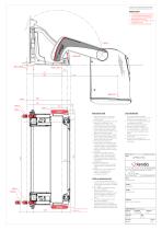
DO NOT SCALE FROM THIS DRAWING, WORK TO FIGURED DIMENSION ONLY. GENERAL NOTES 1. All loading drawings are to be read in conjunction with the relevant load calculations and allowing for apropriate local factors. 2. All dimensions and setting out to be confirmed on site. 3. For other notes refer to drawing Pool waterline Note 6. (Rb) Note 1. Load Foot Right INSTALLATION NOTES LOAD ASSUMPTIONS 1. Telescopic rear foot. Downward pressure is spread over the red hatched area. 2. Upward loads, generated when the platform is over the pool, are transferred via the black circular anchor sockets (one at each side). 3. The "standard" telescopic adapter positions the anchor hole at a set back variable between 760mm and 885mm from the pool edge. 4. The "extra long" telescopic adapter positions the anchor hole at a set back variable between 890mm and 1035mm from the pool edge. 5. Front foot pivots through a horizontal axis - load is spread over the hatched area. Drawing shows standard version. Various additional options available to spread loads into deck and span deck channels if required. 6. Hold down load (Rb) - position variable - taken at closest to pool edge for worst case calculation. 7. Pool lift upward support load (Ra) (transmitted via the load foot) acts at position 7. 8. Pool lift self weight (W) 9. Platform Load (F) taken as acting 1/3rd back from the platform front edge 10. Circular arc of arm - taken in the position that generates the maximum moment and consequential loads. 1. The load is applied centrally between the two anchor points and shared evenly between them. 2. A factor of 1.6 is applied to the Safe working load in line with international design standards. 3. Effects of bouyancy ignored 4. Combined platform weight (users plus wheelchairs) occurs 31 of the way back from the platform front edge. 5. Shortest anchor set back is used (worst case) 6. Poolpod is considered in the position where it is furtherst from the pool edge Load Foot Left Recommended Pool edge line 1. F = 1961 N (factored load with a safety factor of 1.6) This is based on a safe working load (SWL) of 250Kgs. 2. W = 2452N 3. Rb = 4293 N (generated at each side of the platform) Creates a downthrust on the suporting structure, applied at each front foot (4293N at the left front foot and 4293N at the right front foot). 4. Ra = 8707 N (generated at each side of the platform) Creates an uplift force on the supporting structructure applied at each anchor position (7536N at the left side and 7536N at the right side) LOADS on supporting structure Sheet Title DECK LOAD DIAGRAM Project Reference: POOLPOD File Name
Open the catalog to page 1All Cotenda catalogs and technical brochures
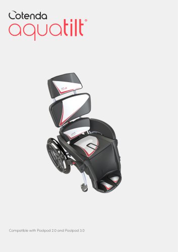 Pool Wheelchair
13 Pages
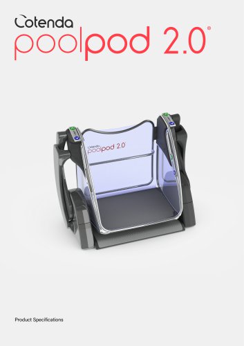 Poolpod 2.0
7 Pages
 poolpod 3.0®
7 Pages

- Outdoor wheelchair
- Indoor wheelchair
- Wheelchair with legrest
- Manual wheelchair
- Black wheelchair
- Height-adjustable wheelchair
- Reclining wheelchair
- Wheelchair with headrest
- Wheelchair with armrests
- Gray wheelchair
- Steel frame wheelchair
- Red wheelchair
- White wheelchair
- Commode wheelchair
- Shower wheelchair
- Pool wheelchair
- Disabled people pool lift
- Wheelchair pool lift