EMG Signal Quality
1 /6Pages

EMG Signal Quality
1 /6Pages
Catalog excerpts

Technical Note 102: EMG Signal Quality Purpose This technical note addresses factors that must be considered in verifying that quality EMG data is being acquired. It assumes that the EMG sensor has already been located properly. Please see Technical Note 101: EMG Sensor Placement for more details. Hardware Concepts • • • • Baseline Noise Line Interference Clipping Amplifier Gain Software Concepts • Error Indicators • Domain • Range www.delsys.com
Open the catalog to page 1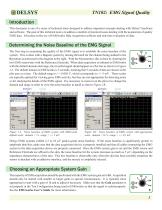
Introduction This document is one of a series of technical notes designed to address important concepts dealing with Delsys® hardware and software. The goal of this technical note is to address a number of practical issues dealing with the acquisition of quality EMG data. It focuses on the use of EMGworks Data Acquisition software and real-time evaluation of data. Determining the Noise Baseline of the EMG Signal The first step in examining the quality of the EMG signal is to establish the noise baseline of the system. This is done with a Bagnoli system by turning the knob for the channel being...
Open the catalog to page 2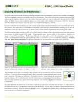
Ensuring Minimal Line Interference Any EMG system is susceptible to ambient noise that originates from electromagnetic sources in the recording environment. The most important component of ambient noise is line interference. This refers to noise that originates from power line sources (power supplies, electrical wire, light bulbs, fluorescent lamps, etc.) that is undesirably recorded with the EMG signal. In North America, line interference appears as a cyclic signal with a fundamental frequency of 60 Hz. In Europe and other international countries, this cyclic signal has a fundamental frequency...
Open the catalog to page 3
Large amplitude line interference is difficult to overlook since it is difficult to clearly see EMG activity within this signal. Low amplitude line interference is sometimes not detected, however. The example below shows low amplitude line interference due to poor EMG sensor to skin contact. The hair was not shaved at the detection site and no skin cleaning was performed. The same signal could result from an unconnected EMG sensor or poor Reference Electrode to skin contact. In Figure 3A, a low amplitude signal is present, but the source is not clear. The Line error indicator is illuminated,...
Open the catalog to page 4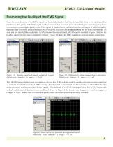
Examining the Quality of the EMG Signal Once the noise baseline of the EMG signal has been studied and it has been assured that there is no significant line interference, the quality of the EMG signal can be examined. It is important not to immediately proceed to large amplitude contractions in assessing the quality of the EMG signal. It should first be confirmed that the recording is of sufficient quality that individual motor unit action potentials (MUAPs) can be discerned (See Technical Note 101 for more information). As soon as a few muscle fibers underneath the EMG sensor become activated,...
Open the catalog to page 5
Once it has been confirmed that quality motor unit action potentials are being recorded, the full range the EMG signal can be examined. In Figure 7, the subject began with the muscle being studied completely relaxed. The amount of contraction was then gradually increased from a level where individual MUAPs could be observed to the level of maximal contraction. Figure 7: EMG activity during a task of increasing muscle activity. Individual motor unit action potentials are noticeable in the early recording and could be clearly seen if zoomed. Maximal EMG amplitude never exceeds 4.5 mV. Default scale:...
Open the catalog to page 6All Delsys catalogs and technical brochures
 EMG Signal Analysis
5 Pages
 EMG Sensor Placement
10 Pages
 Delsys Product Catalog (2021)
19 Pages

- Analysis software
- Tablet computer software
- Tablet PC software
- Control software
- Windows software
- Monitoring software
- Design software
- Software module
- Data management software
- Recording software
- Server software
- Data analysis software
- EMG system
- Module
- Analysis software module
- Medical software module
- Portable EMG
- Electrocardiography software
- Modeling software