Synchronization and Triggering
1 /4Pages

Synchronization and Triggering
1 /4Pages
Catalog excerpts

Technical Note 301: Synchronization and Triggering Purpose The need to synchronize data from more than one measurement system often arises during physiological studies. This Technical Note focuses on important concepts concerning synchronization and triggering. It focuses on general examples. Please see Technical Note 302: Myomonitor Data Synchronization for detailed instructions regarding a specific situation. Synchronization Concepts • • • • • • • Primary Data Acquisition System Secondary Data Acquisition System Constant Time Delays Variable Time Delays Start Trigger Input Start Trigger Output Stop Triggers Triggering Scenarios • Primary/Secondary Triggering • Independent-Signal Triggering • Common Signal Synchronization www.delsys.com
Open the catalog to page 1
The Need for Synchronization Physiological studies often utilize a variety of specialized measurement systems in experimental designs. The ideal case employs a single data acquisition system that records all necessary data types, inherently time-synchronizing all measurements. In many cases, however, it is necessary to have multiple data acquisition systems that are specifically designed for only one type of measurement. An example that is often encountered in the Biomechanics field is the need to record EMG data from the body’s muscles as well as Motion Capture data from the body’s movements....
Open the catalog to page 2
The Concept of Triggering The key to implementing a successful triggering strategy is to establish a control signal that is capable of immediately starting data acquisition on one or more systems. The ability for a data acquisition system to start with a digital control signal is usually described as a Start Trigger Input. The ability for a data acquisition system to start other systems with a digital control signal is usually described an a Start Trigger Output. In most cases, the specifications of these control signals are 5V digital pulses whose polarity and width will vary for different manufacturers....
Open the catalog to page 3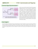
Common Signal Synchronization Measurement Data Input A Push Button Switch Measurement Data Input B Primary Data Acquisition System (A) Primary Data Acquisition System (B) Figure 5: A common signal is sampled by both measurement systems so that the same time marker exists in all data sets. This may require dedicated data channels. In those cases where data acquisition systems do not support triggering functions, it may be possible to establish time synchronization of data by measuring a signal that is common to all systems. This is usually accomplished by sending an electrical pulse to one channel...
Open the catalog to page 4All Delsys catalogs and technical brochures
 EMG Signal Analysis
5 Pages
 EMG Signal Quality
6 Pages
 EMG Sensor Placement
10 Pages
 Delsys Product Catalog (2021)
19 Pages
- Analysis software
- Tablet computer software
- Tablet PC software
- Control software
- Windows software
- Monitoring software
- Design software
- Acquisition software
- Software module
- Data management software
- Recording software
- Server software
- Data analysis software
- EMG system
- Module
- Analysis software module
- Medical software module
- Portable EMG
- Electrocardiography software
- Modeling software