
- Catalogs
- DENTAL TECH S.R.L.
- D-77 LOGIC SPHERO

D-77 LOGIC SPHERO
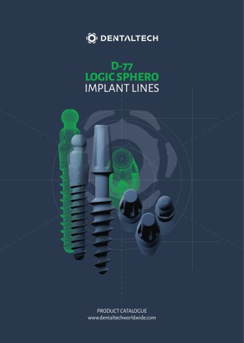
D-77 LOGIC SPHERO
The BWS® implant surface is treated with sandblasting and acid etching to enhance roughness, promoting fibrin adhesion and bone healing. This process facilitates contact osseointegration by supporting osteoblast migration and new bone formation on the titanium surface. Each batch undergoes SEM control and Argon Cold Plasma cleaning to minimize contamination.
The D-77 implant features compressive threads for multiple unit restorations with immediate loading. It supports both flap and flapless placement and can be bent up to 15 degrees if high primary stability is achieved. Available in various lengths and diameters, it requires specific surgical sequences and drill speeds based on clinical evaluation.
Drill stops ensure optimal depth control during surgery, reducing risk and stress. Proper insertion and removal procedures are outlined for safety and efficiency.
Components include impression copings, implant analogs, and various abutments made from materials like Ti5 and Pmma. Digital flow components support CAD-CAM and 3D printing applications.
The Logic Sphero system offers small diameter implants for stabilizing total prostheses. Made from Titanium Gr5, these implants provide excellent mechanical resistance and are designed for minimally invasive surgery, ensuring maximum bone surface contact and primary stability.
Detailed procedures for inserting Logic Sphero implants emphasize torque limits and correct placement to avoid tissue compression. Maintenance of surgical instruments, including cleaning and sterilization, is crucial for longevity and effectiveness.
Dental Tech tools are supplied non-sterile and require cleaning and sterilization before use. A validated manual cleaning method using a peracetic acid-based solution is recommended.
Equipment should be disinfected using a 4% peracetic acid solution for 15 minutes, avoiding glutaraldehyde or sodium hypochlorite. After disinfection, rinse thoroughly and inspect for organic remains, scrubbing outer parts with a non-metal bristled brush. Use an ultrasound bath for manual rinsing followed by careful rinsing.
To prevent damage to bone tissue and ensure proper osseointegration, use drills with gradual diameter progression, limit osteotomy speed to 800 RPM, and tapping speed to 20 RPM. Maintain axial alignment, avoid lateral pressure, and use light pressure with back-and-forth movements. Ensure irrigation canals are clear and avoid cooling instruments with air-water syringes. For taps, do not exceed 55N/cm force with micromotors.
Dry equipment thoroughly and seal individually for moist heat sterilization. Dental Tech recommends a 3-minute cycle at 134°C. Post-sterilization, store instruments in a dry, dust-free environment, opening packages only before use. Check instruments for corrosion or damage after cleaning, using a magnifying lens for concealed areas. Dispose of damaged instruments according to waste management laws.
Dispose of medical devices per national waste management laws. Use of non-original components may void warranties and compromise functionality. Instructions are recommendations and users should ensure product adequacy through training.
Orders imply acceptance of sale conditions. The company may modify prices without notice, and goods travel at customer risk. Payment terms must be adhered to, and claims for defects must be made within 8 days of receipt. Italian law governs disputes.
Various trademarks are registered by Dental Tech and other companies. Materials used include cobalt-chrome alloy, surgical stainless steel, and medical-grade titanium.
Catalog excerpts
IMPLANT LINES PRODUCT CATALOGUE www.dentaltechworldwide.com
Open the catalog to page 1
BWS® Implant Surface 4 Implant line D-77 Compressive threads 5 Diameter 3.25 - Recommended surgical sequence and drill speed 6 Diameter 4.0 - Recommended surgical sequence and drill speed 7 Diameter 4.75 - Recommended surgical sequence and drill speed 8 Drills - Reading depth notches and sharp drills 9 Drill Stop - Stop insertion and removal procedure 10 D-77 prosthetic components for digital flow 12 Implant line LOGIC SPHERO - Mini implant system 14 Logic Sphero insertion procedure 15 Logic Sphero prosthetic components 16 Logic Sphero surgical instruments 17 Dynamometric ratchet cleaning and...
Open the catalog to page 3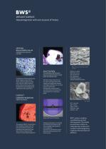
SANDBLASTING AND ACID ETCHING Sandblasting and etching processes of the implant surface allow to obtain optimal roughness values that make the adhesion of fibrin to the surface more tenacious and facilitate the bone healing process, significantly reducing the time. FIBRIN ADHERENCE The capacity of BWS® to retain fibrin, lets osteoblasts migrate from the bone to the implant surface and reproduce there, generating new bone in direct contact with the titanium (contact Osseointegration). THE IMPLEMENTED PROTOCOL PROVIDES VERIFICATION OF EACH BATCH OF PRODUCTION After the surface treatment and the...
Open the catalog to page 4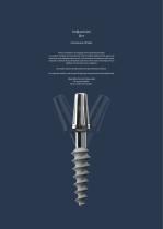
Implant Line D77 Compressive threads The D-77 implant is an implant with compressive threads. lt is used far multiple unit restorations with immediate loading in the upper and lower jaws with adequate bone tissue. lt can be used in combination with others implants and allows flap and flapless placement. If the implant has high primary stability it can be bent up to 15 degrees. One-piece implant Simple placement & prosthetic procedure. For single & multiple unite cement & telescopic restorations with bendable neck. Adjustable abutment slope angle. No pumping effect. Bone condensation design.
Open the catalog to page 5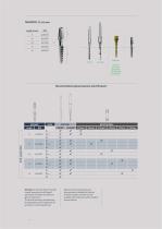
USE ONLY IN CASE OF DENSE BONE OR FOR BONE EXPANSION Recommended surgical sequence and drill speedBONE REF DRILL REF STOP DRILL Lenght Warning ! In the table “Recommended surgical sequence and drill speed” parameters should be considered as general indications. The clinical evaluation should always be subjected to careful analysis by the practitioner in each specific case. Based on the clinical features and bone consistency detected at the time of implant surgery, the choice of the available instrumentation will be made by the practitioner.
Open the catalog to page 6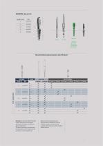
BOE35816 USE ONLY IN CASE OF DENSE BONE OR FOR BONE EXPANSION Recommended surgical sequence and drill speed IMPLANT Lenght checkmark checkmark checkmark checkmark checkmark checkmark Warning ! In the table “Recommended surgical sequence and drill speed” parameters should be considered as general indications. The clinical evaluation should always be subjected to careful analysis by the practitioner in each specific case. checkmark checkmark checkmark checkmark Based on the clinical features and bone consistency detected at the time of implant surgery, the choice of the available instrumentation...
Open the catalog to page 7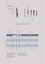
USE ONLY IN CASE OF DENSE BONE OR FOR BONE EXPANSION Recommended surgical sequence and drill speed IMPLANT Lenght checkmark checkmark checkmark checkmark Warning ! In the table “Recommended surgical sequence and drill speed” parameters should be considered as general indications. The clinical evaluation should always be subjected to careful analysis by the practitioner in each specific case. Based on the clinical features and bone consistency detected at the time of implant surgery, the choice of the available instrumentation will be made by the practitioner.
Open the catalog to page 8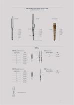
Lance drill - Final drill - Bone expander Lance drill Final drill Bone expander Drill Stop STOP 0 4-5 mm Material: Ti5 Length (L) mm REF Drill Material: Inox
Open the catalog to page 9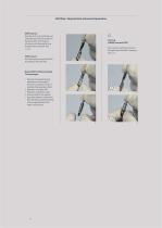
Drill Stop - Stop insertion and removal procedure STOP insertion Hold the drill on the stalk side and insert the stop, with the retentions facing the drill, until the point of contact with the metallic stop located on the drill itself. (Fig. 1 - 2- 3). STOP removal Hold the stop and remove the drill by pulling on the stalk side. Warning WRONG insertion STOP Stop insertion with the retentions facing the tip of the drill is incorrect. (fig. 4 - 5). Depth STOP for different lengths. The advantages: » Optimal check-depth during preparation of the surgical site, even in conditions of poor visibility...
Open the catalog to page 10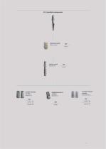
Impression coping Material:Peek Straight abutment shoulder Material:Ti5 Angled abutment 10° shoulder Material:Ti5 Castable abutment shoulder Material:Pmma
Open the catalog to page 11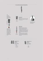
D-77 prosthetic components for digital flow WARNING DO NOT orient the Scan Abutment in other unsuitable positions Correct orientation Scan abutment Material: Ti5 Digital CAD-CAM intraoral scan and laboratory scan. For single and multiple cemented elements. Always match the smaller portion of the Scan Abutment, which is oriented on the hexagon side of the connection, with the milling on the cylindrical portion of the digital analog body. Straight abutment shoulder Material:Ti5 Digital library stock abutment available. Scan abutment removal procedure using screw with screwdriver Digital analog...
Open the catalog to page 12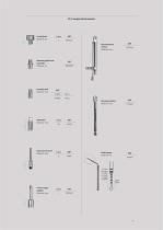
Universal ratchet Material: Inox Extension L mm REF Material: Inox Extension for drill Material: Inox Depth gauge Material: Ti5
Open the catalog to page 13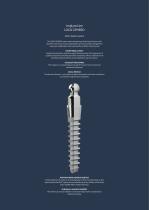
Implant Line LOGIC SPHERO Mini implant system The LOGIC SPHERO system meets the growing clinical need to have small diameter implants for instant stabilisation of total prostheses. Designed for long-term rehabilitation and conceived for excellent clinical results. EXCEPTIONALLY EASY Implant characteristics make the surgical phase very easy. The ergonomics of supplied components facilitate prosthetic procedures. Hence, implants can be inserted and the prosthesis can be stabilised in just one session. EXCELLENT RESISTANCE The implant is a monocomponent made of Titanium Gr5 for maximum mechanical...
Open the catalog to page 14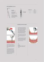
Sphere DIAMETER - Ø 2.25 mm Load direction 2.25 Static load Breakage at N 1500 Transmucosal area L 2,5 mm Stress resistance N 505 x 5,000,000 cycles No breakages 20° The tests were performed on devices with Ø2mm to evaluate either the same or higher diameters. Logic Sphero insertion procedure Complete the insertion of the Logic Sphero implant by using the contraangle assembled with the dedicated adaptor to screw it on, leaving the entire hexagonal portion that is under the sphere outside the soft tissue. This will prevent the O-RING retention device from causing compression of soft tissues (Fig....
Open the catalog to page 15All DENTAL TECH S.R.L. catalogs and technical brochures
 SLIM
SLIM28 Pages
 TISSUE LEVEL
28 Pages
 FTK
FTK28 Pages
 FTZ
FTZ28 Pages
- Dental surgery instrument kit
- Dental implant
- Titanium dental implant
- Conical dental implant
- Dental implant surgery instrument kit
- Bone substitute
- Hexagonal dental implant
- Narrow dental implant
- Internal hexagon dental implant
- Rough dental implant
- Self-tapping dental implant
- Dental sugery bone substitute
- Granules bone substitute
- Screw dental implant
- Collagen tissue matrix
- One-piece dental implant
- Cylindro-conical dental implant
- Absorbable tissue matrix
- Buccal tissue matrix
- Dental clinic dental implant