

FTK
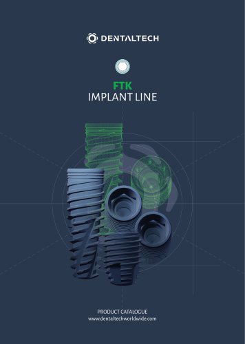
FTK
The BWS® implant surface is treated with sandblasting and acid etching to achieve optimal roughness, enhancing fibrin adhesion and promoting osseointegration. This process is verified by SEM control and further cleaned with Argon Cold Plasma to minimize contamination. Packaging occurs in ISO 7 clean rooms, and gamma-ray sterilization ensures contaminant destruction.
The FTK implant line includes cylindrical and conical designs with conical sealing and hex connections. Available in various lengths and diameters, these implants feature micro-grooves to limit bone resorption and a spiral profile for better penetration.
Drills are designed with depth notches and sharp edges for precise surgical procedures. Drill stops are available for different lengths, ensuring optimal depth control and reducing surgical risks. Proper insertion and removal procedures are outlined to enhance safety.
Recommended surgical sequences and drill speeds are provided, with parameters serving as general guidelines. Clinical evaluation should be conducted by practitioners based on specific cases and bone consistency.
Implant drivers are available for both contra-angle and manual use. Detailed procedures for implant insertion, including bi-phase and monophasic techniques, are provided with specific RPM and torque settings.
Components for cemented/screwed prostheses include various abutments and impression copings. MUA components are also detailed, with specific materials and fastening screws included.
Components suitable for digital CAD-CAM and traditional techniques are outlined, including scan abutments and bonding bases. Specific instructions for digital analogs and MUA connections are provided.
Overdenture abutments compatible with Zest LOCATOR® are available, with various height options and included transfer components.
The document outlines various dental instruments and components, specifying materials such as Inox (surgical stainless steel) and Ti5 (Titanium grade V ELI for medical use). It includes details on extensions, depth gauges, parallel pins, screwdrivers, and adaptors, with specific dimensions and references.
Detailed cleaning and maintenance procedures for the dynamometric ratchet are provided, emphasizing disassembly, cleaning with non-metallic brushes, and reassembly. The document also covers manual cleaning and disinfection methods using peracetic acid solutions, and the importance of immediate post-surgery cleaning.
The document stresses the importance of using instruments for their intended purposes, maintaining them properly, and adhering to recommended torque values to avoid compromising screw integrity. It advises on manual screw insertion and final tightening with appropriate tools.
Dental Tech tools are supplied non-sterile and must be washed and sterilized before use. The document validates specific sterilization cycles and emphasizes checking instruments for damage post-cleaning.
Guidelines for surgical instrument use include gradual diameter progression for drills, RPM limits during osteotomy, and the necessity of irrigation. It warns against lateral pressure and excessive force during procedures.
Post-sterilization, instruments should be stored in a dry, dust-free environment. Disposal must comply with national waste management laws.
The document warns against using non-original components and emphasizes user responsibility for ensuring product adequacy through training.
A comprehensive bibliography is provided, citing studies on titanium implants and surface topography.
The document includes trademark information and sale conditions, highlighting the jurisdiction of the Court of Milano for disputes.
Catalog excerpts
PRODUCT CATALOGUE www.dentaltechworldwide.com
Open the catalog to page 1
BWS® Implant Surface 4 FTK Implant line (Cylindrical / Conical) 5 Drills - Reading depth notches and sharp drills 7 Lance drill - Parallel drills - Countersink - Tappers 7 Drill Stop - Stop insertion and removal procedure 8 Recommended surgical sequence and drill speed 9 Implant Drivers - Implants insertion procedure 11 Components for cemented/screwed prosthesis 12 Components for MUA screwed prosthesis 13 Prosthetic components for digital flow 14 Prosthetic components for digital flow - Connection on MUA 17 Overdenture prosthetic components 18 Instruments for subcrestal implant placement 20 Dynamometric...
Open the catalog to page 3
SANDBLASTING AND ACID ETCHING Sandblasting and etching processes of the implant surface allow to obtain optimal roughness values that make the adhesion of fibrin to the surface more tenacious and facilitate the bone healing process, significantly reducing the time. FIBRIN ADHERENCE The capacity of BWS® to retain fibrin, lets osteoblasts migrate from the bone to the implant surface and reproduce there, generating new bone in direct contact with the titanium (contact Osseointegration). THE IMPLEMENTED PROTOCOL PROVIDES VERIFICATION OF EACH BATCH OF PRODUCTION After the surface treatment and the...
Open the catalog to page 4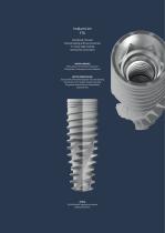
Implant Line FTK Cylindrical / Conical Conical sealing and hex connection 11° morse Taper locking Internal hex connection MICRO-GROOVES Micro-grooves to limit bone resorption. The implant’s screwing axis can be adjusted. BETTER PENETRATION Spiral profile with hybrid progress: flat and radiating towards the root, trianglar-shaped externally, for greater penetration into incompletely prepared sites. APICAL With helicoidal progress to enhance stable penetration.
Open the catalog to page 5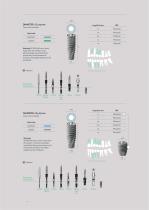
DIAMETER - Ø 3.75 mm Cover screw included Color Code Warning! All DRP drills are 0.8 mm longer than the implant. In the planning stage and while drilling in proximity to vital anatomical structures, this added length must be considered. radio-checked Optional Indication of surgical position Recommended surgical sequence Cover screw included Color Code Warning! All DRP drills are 0.8 mm longer than the implant. In the planning stage and while drilling in proximity to vital anatomical structures, this added length must be considered. 3.05 2.9 Indication of surgical position radio-checked Optional...
Open the catalog to page 6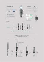
Cover screw included Color Code Warning! All DRP drills are 0.8 mm longer than the implant. In the planning stage and while drilling in proximity to vital anatomical structures, this added length must be considered. Indication of surgical position radio-checked Optional Recommended surgical sequence Drills - Reading depth notches and sharp drills Lance drill - Parallel drills - Countersink - Tappers Lance drill Parallel drills The colored rings identify the diameter of the surgical line
Open the catalog to page 7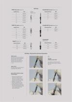
Drill Stop Parallel drill L 23 mm Material: Inox Material: Inox Drill Stop - Stop insertion and removal procedure STOP insertion Hold the drill on the stalk side and insert the stop, with the retentions facing the drill, until the point of contact with the metallic stop located on the drill itself. (Fig. STOP removal Hold the stop and remove the drill by pulling on the stalk side. Depth STOP for different lengths. » Optimal check-depth during preparation of the surgical site, even in conditions of poor visibility of the operating field; » Reduction of surgical risk; » Reduction of operator stress;...
Open the catalog to page 8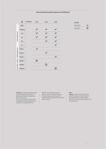
checkmark checkmark checkmark checkmark checkmark checkmark checkmark checkmark LEGEND REQUIRED checkmark OPTIONAL radio-checked Warning ! In the table “Recommended surgical sequence and drill speed” parameters should be considered as general indications; the clinical evaluation should always be subjected to careful analysis by the practitioner in each specific case. Based on the clinical features and bone consistency detected at the time of implant surgery, the choice of the available instrumentation will be made by the practitioner. Tappers may be used at the operator's discretion, based on...
Open the catalog to page 9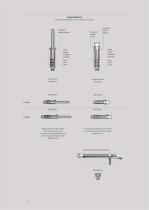
Implant Drivers Implant CA connection - Implant ratchet connection Hexagonal implant reference Depth notches for flapless technique Hexagonal head for ratchet Hexagonal implant reference Depth notches for flapless technique Implant ratchet connection Allows removal of the implant from the ampoule and its insertion in the surgical site using the contra-angle implant driver. Material: Inox A tool to be connected to the ratchet to complete insertion of the implant. Material: Inox
Open the catalog to page 10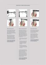
With manual implant driver Insert the implant driver connected to the handwheel into the implant making a slight rotation to allow good matching of the two geometric figures (implant - driver) and remove the implant (Fig. 6). Begin insertion of the implant in the alveolar surgical site using the manual implant driver. Where bone density permits, it is possible complete insertion of the implant using the manual wrenches (Fig. 7). To remove, exercise a slight lateral movement, right and left, in order to free the matching (Fig. 7). Insert the direct contra-angle implant driver into the implant...
Open the catalog to page 11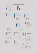
Components for cemented/screwed prosthesis Parallel healing abutment Material: Ti5 H Taper healing abutment Material: Ti5 H Closed tray impression coping Material: Ti5 Fastening screw included REF VOS1109 Open tray impression coping Material: Ti5 Fastening screw included REF VOS1110 Transfer SNAP* Material: Peek Recommended in combination with the OS1109 transfer for better stability in the impression material. Package 4 pcs. Implant analog Material: Ti5 ML Fastening screw included REF VFOSAP Straight abutment Material: Ti5 Castable abutment Material: Pmma Straight abutment Material: Ti5 Package...
Open the catalog to page 12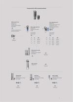
MUA protection cap Material: Ti5 Package 2 pcs. Fastening screw included REF VPCEM Use only on abutments from REFOS1130 to OS1136 Supplied with transfer handle H[ MUA angled abutment Material: Ti5 Supplied with transport and parallelization screw Fastening screw included REF VFOSAP MUA precision transfer Material: Ti5 Fastening screw included REF VFTEM Fastening screw included REF VPCEM MUA castable Material: Pmma Fastening screw included REF VPCEM
Open the catalog to page 13All DENTAL TECH S.R.L. catalogs and technical brochures
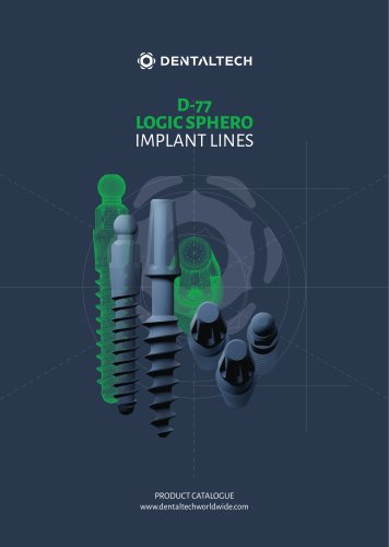 D-77 LOGIC SPHERO
24 Pages
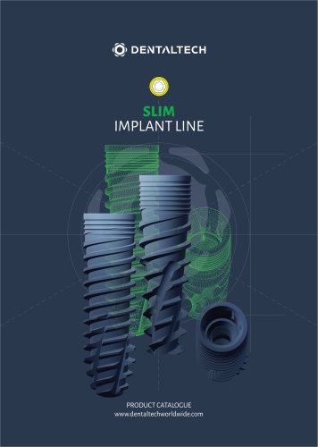 SLIM
SLIM28 Pages
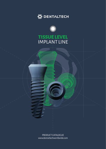 TISSUE LEVEL
28 Pages
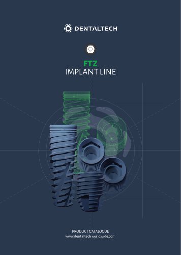 FTZ
FTZ28 Pages
- Dental surgery instrument kit
- Dental implant
- Titanium dental implant
- Conical dental implant
- Dental implant surgery instrument kit
- Bone substitute
- Hexagonal dental implant
- Narrow dental implant
- Internal hexagon dental implant
- Rough dental implant
- Self-tapping dental implant
- Dental sugery bone substitute
- Granules bone substitute
- Screw dental implant
- Collagen tissue matrix
- One-piece dental implant
- Cylindro-conical dental implant
- Absorbable tissue matrix
- Buccal tissue matrix
- Dental clinic dental implant