
- Catalogs
- DENTAL TECH S.R.L.
- TISSUE LEVEL

TISSUE LEVEL
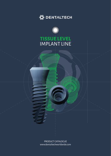
TISSUE LEVEL
Catalog excerpts
PRODUCT CATALOGUE www.dentaltechworldwide.com
Open the catalog to page 1
BWS® Implant Surface 4 TISSUE LEVEL Implant Line 5 Drills - Reading depth notches and sharp drills 7 Drill Stop - Stop insertion and removal procedure 8 Recommended surgical sequence and drill speed 9 Implant Drivers - Implants insertion procedure 11 Components for cemented/screwed prosthesis on one piece abutment 12 Prosthetic components for digital flow 13 Components for OCTA connections prosthesis 15 Prosthetic components for digital flow - Connection on OCTA 16 Overdenture prosthetic components 17 Dynamometric ratchet cleaning and maintenance 20 Spare Screws Available 21 Preliminary indications...
Open the catalog to page 3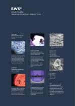
SANDBLASTING AND ACID ETCHING Sandblasting and etching processes of the implant surface allow to obtain optimal roughness values that make the adhesion of fibrin to the surface more tenacious and facilitate the bone healing process, significantly reducing the time. FIBRIN ADHERENCE The capacity of BWS® to retain fibrin, lets osteoblasts migrate from the bone to the implant surface and reproduce there, generating new bone in direct contact with the titanium (contact Osseointegration). THE IMPLEMENTED PROTOCOL PROVIDES VERIFICATION OF EACH BATCH OF PRODUCTION After the surface treatment and the...
Open the catalog to page 4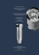
Tissue Level Implant Line Internal design: cone with anti-rotational octagon Conical sealing and octagon connection 8° morse taper locking Combines the benefits of the conical seal with those of internal anti-rotational structures, conveying both biological and mechanical stability to the prosthetic components without complicating the prosthetist and dental technician’s work. POLISHED CROWN PORTION The 1,5 mm polished transmucosal portion allows to better manage the transgingival path. MICRO-GROOVES Micro-grooves to limit bone resorption. The implant’s screwing axis can be adjusted. BETTER PENETRATION...
Open the catalog to page 5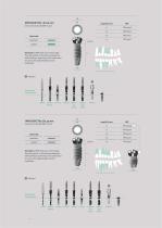
IMPLASSIC TR3 - Ø 3.75 mm Cover screw included (REF 112201) Color Code Warning! All DRP drills are 0.8 mm longer than the implant. In the planning stage and while drilling in proximity to vital anatomical structures, this added length must be considered. 3.75 Indication of surgical position radio-checked Optional radio-checked Recommended surgical sequence Cover screw included (REF 112201) Color Code Warning! All DRP drills are 0.8 mm longer than the implant. In the planning stage and while drilling in proximity to vital anatomical structures, this added length must be considered. 4.25 Indication...
Open the catalog to page 6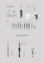
Color Code Cover screw included (REF 112201) Warning! All DRP drills are 0.8 mm longer than the implant. In the planning stage and while drilling in proximity to vital anatomical structures, this added length must be considered. 4.75 Indication of surgical position radio-checked Optional radio-checked Recommended surgical sequence Drills - Reading depth notches and sharp drills Lance drill - Parallel drills - Tappers Lance drill Parallel drills The colored rings identify the diameter of the surgical line
Open the catalog to page 7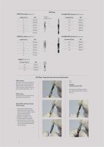
Drill stop Parallel drill L 23 mm Material: Inox Length (0) mm REF Parallel drill L 23 mm Material: Inox Drill Stop - Stop insertion and removal procedure STOP insertion Hold the drill on the stalk side and insert the stop, with the retentions facing the drill, until the point of contact with the metallic stop located on the drill itself. (Fig. 1 - 2- 3). STOP removal Hold the stop and remove the drill by pulling on the stalk side. Depth STOP for different lengths. The advantages: » Optimal check-depth during preparation of the surgical site, even in conditions of poor visibility of the operating...
Open the catalog to page 8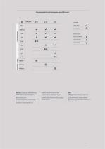
LEGEND REQUIRED checkmark OPTIONAL radio-checked Warning ! In the table “Recommended surgical sequence and drill speed” parameters should be considered as general indications; the clinical evaluation should always be subjected to careful analysis by the practitioner in each specific case. Based on the clinical features and bone consistency detected at the time of implant surgery, the choice of the available instrumentation will be made by the practitioner. Note Tappers may be used at the operator's discretion, based on the bone density encountered and to reduce insertion torque stress during...
Open the catalog to page 9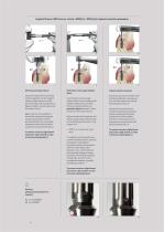
Implant Drivers (REF 001145 - 001156 - RDC3727 - RDC3732) Implants insertion procedure With manual implant driver Insert the implant driver connected to the handwheel, into the implant making a slight rotation to allow good matching of the two geometric figures (implant - driver) and remove the implant (Fig. 6). Begin insertion of the implant in the alveolar surgical site using the manual implant driver. Where bone density permits, it is possible complete insertion of the implant using the manual wrenches (Fig. 7). To remove, exercise a slight lateral movement, right and left, in order to free...
Open the catalog to page 10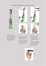
MOUNT with screw (REF MTR008 - MTR009) Implants insertion procedure Insert the short or long MOUNT depending on the desired vertical dimension; ensure that the octagon of the instrument is properly engaged with the implant connection and tighten manually using a manual screwdriver, applying a maximum torque of 10 Ncm (Fig. 14) Remove the implant from the ampoule manually and begin inserting the implant into the previously prepared surgical socket. (Fig. 15-16) Remove the implant from the ampoule mechanically using the contra-angle adapter and begin inserting the implant into the previously prepared...
Open the catalog to page 11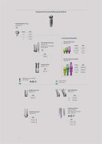
Components for cemented/screwed prosthesis Healing abutment - Ø 5.5 Material: Ti5 on one piece abutment One piece abutment Material: Ti5 Pick up impression copy Material: Ti5 Fastening screw included REF VTPR108 TPR108 One piece abutment analog Material: Ti5 Implant analog Material: Ti5 REF AGT128 Fastening screw included* REF VDT608 Straight abutment* Material: Ti5 Cylinder abutment* Material: Ti5 Angled abutment* Material: Ti5 REF 15° Castable abutment Material: Pmma Fastening screw included REF 112218/VP
Open the catalog to page 12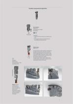
Prosthetic components for digital flow Scan abutment Material: Ti5 Fastening screw included REF VDT608 REF SCANHX35 Suitable for » Digital CAD-CAM intraoral scan and laboratory scan. » For single cemented and screwed elements. For multiple cemented elements. Digital analog Material: Ti5 Correct orientation WARNING DO NOT orient the Scan Abutment in other unsuitable positions. Analog for digital models, specific for applications through the manufacture of models made with 3D printing/prototyping. The characteristic shape with rounded edges, allows easy insertion into the model seat, without interference...
Open the catalog to page 13All DENTAL TECH S.R.L. catalogs and technical brochures
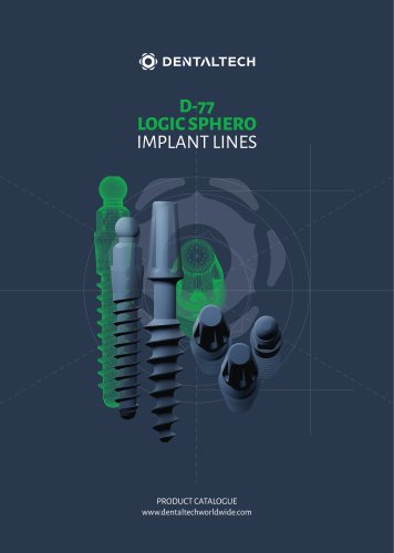 D-77 LOGIC SPHERO
24 Pages
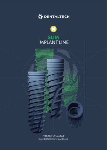 SLIM
SLIM28 Pages
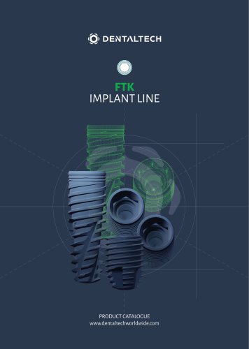 FTK
FTK28 Pages
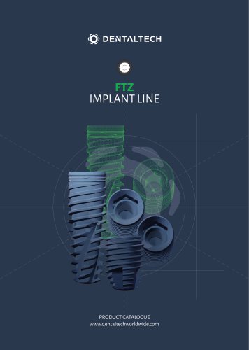 FTZ
FTZ28 Pages
- Dental surgery instrument kit
- Titanium dental implant
- Conical dental implant
- Dental implant surgery instrument kit
- Bone substitute
- Hexagonal dental implant
- Narrow dental implant
- Internal hexagon dental implant
- Rough dental implant
- Self-tapping dental implant
- Dental sugery bone substitute
- Granules bone substitute
- Screw dental implant
- Collagen tissue matrix
- One-piece dental implant
- Cylindro-conical dental implant
- Absorbable tissue matrix
- Buccal tissue matrix
- Dental clinic dental implant