Overdenture System

Overdenture System
Catalog excerpts

Overdenture System Dentium Overdenture System Product Catalog & Manual
Open the catalog to page 1
Overdenture System Overdenture System Mini Ball / Positioner Attachment
Open the catalog to page 3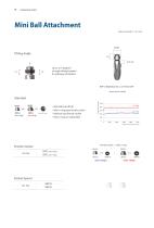
Overdenture System Mini Ball Attachment Unit: mm, Scale 1 : 1.5 / mm Up to +15 degrees of angle tilting freedom for pathway of implant. Mini o-ring • ini ball size (Ø1.8) M • Mini o-ring type female socket • inimal-size female socket M • Mini o-ring are replacable Female Socket + Mini o-ring Ø4.85
Open the catalog to page 4
Mini Ball Attachment Unit: mm, Scale 1 : 1.5 / mm Mini Ball Abutment implantium imrlantilimII SuperLfm Mini Ball Abutment SitnpieLitien Application Mini Ball Abutment nr G/H 1.0 2.0 3.0 4.0 5.0 Angled Mini Ball Abutment NR Diameter
Open the catalog to page 5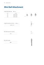
Overdenture System Mini Ball Attachment Angled Mini Ball Cap Angled Overdenture Screw GAOSC 16 19 Mini Ball Impression Coping GICA Mini Ball Analog BANL
Open the catalog to page 6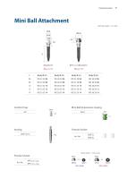
Mini Ball Attachment Unit: mm, Scale 1 : 1.5 / mm Mini Ball Impression Coping GICA Female Socket + Mini o-ring
Open the catalog to page 7
For multiple-unit and full-arch restorations Self Aligning: Self aligning mechanism allows easy and convenient denture placement Tilting Angle: Tilting Type (±10°) / Non Tilting Type (±5°) Four Different Retention Options: 100gf, 300gf, 500gf and 1,000gf Process to make overdenture using the Positioner 1. Non-tiling plastic socket having ±5° is recommended as a standard assembly 2. Make denture based on the white plastic socket having 100gf 3. If the path is not parallel (more than ±5°), use the Tilting Type plastic socket having ±10° 4. Select and use the plastic socket (300gf, 500gf, or 1,000gf)...
Open the catalog to page 8
Overdenture System Positioner Unit: mm, Scale 1 : 1.5 / mm Positioner Abutment Application Positioner Impression Coping Art. No. Positioner Core Tool Art. N
Open the catalog to page 9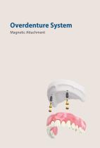
Overdenture System Overdenture System Magnetic Attachment
Open the catalog to page 10
Magnetic Assay Application Implant Keeper Diameter 04.5 Art. No. MKP 45 10 D MKP 45 20 D MKP 45 30 D MKP 45 40 D MKP 45 50 D MKP 45 60 D Note: 1) It is recommended to keep the torque level at 25~30 N-cm to tighten the magnetic abutment with the fixture.
Open the catalog to page 11
Magnetic Assay Application Note: 1) It is recommended to keep the torque level at 25~30 N-cm to tighten the magnetic abutment with the fixture.
Open the catalog to page 12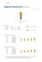
Magnetic Assay 05.5 2.5 X jF fflT 2-° Retention Force 750gf *Note: 1) The NR Line fixture with size of 03.1 straight type is not recommended to use with the screw abutment. Should they be used together, abutment height after assembly will become 1.0mm longer than the other sized fixtures. 2) It is recommended to keep the torque level at 20 N-cm to tighten the magnetic abutment with fixture.
Open the catalog to page 14
Overdenture System Overdenture System Prosthesis Manual
Open the catalog to page 15
Overdenture System Mini Ball Attachment Chairside Connect the mini ball abutment onto the fixture. Affix the impression coping on the mini ball abutment. Take Impression for the making of individual tray. Produce the individual tray for denture impression. Apply the impression material. Take the final impression with the prepared individual tray. After the impression material is set, discard the individual tray. Image of the final impression (with impression coping). Mini ball Analog. Insert analogs into the embedded impression coping. Socket spacer. Fabrication of denture with conventional method....
Open the catalog to page 16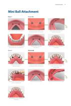
Overdenture System Mini Ball Attachment Case 1 Secure spaces for the female sockets. Connect the female sockets to the mini ball abutments in the intra-oral. Apply small amount of the resin into the secured area. Position the denture in the oral cavity and wait until the resin is completely set. Female sockets are placed in the denture. After polishing and the overdenture is complete. Create holes for placement of female sockets. Connect the female sockets to the mini ball abutments in the intra-oral. Examine the interference between inner surface of the holes and the female sockets. Apply the...
Open the catalog to page 17
Overdenture System Angled Mini Ball Attachment Case 1 Secure spaces for the female sockets. Apply small amount of the resin into the secured area. After polishing and the overdenture is complete. Connect the female sockets to the Angled mini ball abutments in the intra-oral. Position the denture in the oral cavity and wait until the resin is completely set. Female sockets are placed in the denture.
Open the catalog to page 18
Overdenture System Angled Mini Ball Attachment Case 2 Connect the female sockets to the angled mini ball abutments in the intra-oral. Create holes for placement of female sockets. Examine the interference between inner surface of the holes and the female sockets. Apply the resin into the holes and wait until it is completely set. Apply resin around the female sockets. After polishing and the overdenture is complete. Placement the female sockets.
Open the catalog to page 19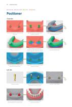
Overdenture System Positioner Chairside Connect the Positioner Abutment onto the fixture. Affix the impression coping on the Positioner Abutment. Take impression for the production of the individual tray Produce the individual tray for denture impression. After connecting the Positioner Abutment and the impression coping together, apply the impression material. Take the final impression with the prepared individual tray. After the impression material is set, discard the individual tray. Image of the set final impression (with impression coping). Positioner Analog. Insert the Positioner Analog...
Open the catalog to page 20
Overdenture System Secure spaces for the female sockets. Place the "block out spacer" on the Positioner Abutment in the patient's mouth. Connect the metal socket onto the Positioner Abutment. Apply a small amount of resin into the space created for the metal socket. Position the denture in the mouth and wait until the resin is completely set. Remove the white plastic socket (100gf) using the positioner tool and replace with a regular plastic of a desired retention force (300, 500 or 1000gf). Remove the denture after the resin is fully set. Image of the denture with the metal socket. Remove the...
Open the catalog to page 21
Overdenture System Magnetic Attachment Chairside After healing abutment removal. Connect implant keeper with fixture and tighten it with 20N·cm. Implant keepers connected with the fixtures. Position the magnetic assay on the implant keeper. Secure spaces for the magnetic assays. Examine the interference between inner divot of the denture and the magnets. Apply resin on the divot of the denture"s inner surface. Position the denture into the mouth and wait until the resin is completely set. Magnetic assays are placed in the denture. Apply some of resin around the magnetic assays. After the resin...
Open the catalog to page 22All Dentium catalogs and technical brochures
 SlimLine
28 Pages
 SuperLine Product
130 Pages
 Instrument Catalog
46 Pages
 Regeneration
26 Pages
 Why Dentium
52 Pages
 Digital dentistry 1403
20 Pages
 lab system
38 Pages
 Dental Lab System
44 Pages
 SlimLine SPM-1403
28 Pages
 Implantium II
68 Pages
![Surgical Guide SGCM-1312 [Rev.1]](https://img.medicalexpo.com/pdf/repository_me/72062/surgical-guide-sgcm-1312-rev1-138906_1mg.jpg) Surgical Guide SGCM-1312 [Rev.1]
Surgical Guide SGCM-1312 [Rev.1]15 Pages
 Paste Stain
2 Pages
 Temporary Shell_1501 1501
4 Pages
 Introduction of Dentium 2014
23 Pages
 Maxillofacial Implant
20 Pages
 Help kit XIH-1301
16 Pages
 SimpleLine II Product
42 Pages
 DASK-1402
12 Pages
 Product from Dentium
48 Pages
 RS Kit RSKP-1308
12 Pages
 GBR system GSPS-1304
16 Pages
 NR Line Product Catalog
49 Pages
 rainbow Porcelain
26 Pages
 Lab Product catalog
24 Pages

Archived catalogs

- Implant abutment
- Titanium implant abutment
- Syringe
- Straight implant abutment
- Dental surgery instrument kit
- Dental implant
- Titanium dental implant
- Internal implant abutment
- Conical dental implant
- Micromotor
- Dental implant surgery instrument kit
- Hexagonal implant abutment
- Bone substitute
- Electric micromotor
- Dental radiography system
- Internal hexagon implant abutment
- Dental implant analog
- Cylindrical dental implant
- Dental milling machine
- Dental micromotor