- Catalogs
- Depuy Synthes
- External Midface Distractor System
External Midface Distractor System
1 /43Pages

External Midface Distractor System
1 /43Pages
Catalog excerpts

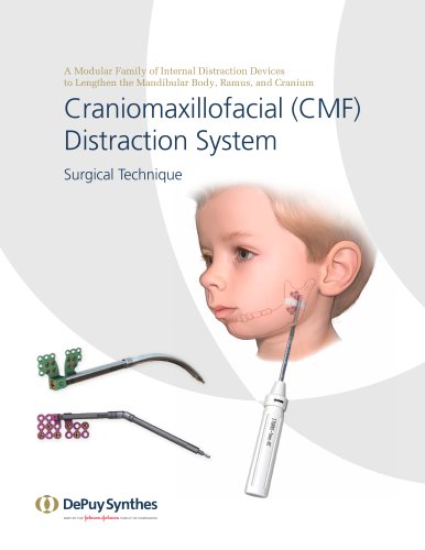
Multiple Pre-, Intra-, and Postoperative Adjustments for Vertical, Horizontal, Sagittal, and Occlusal Vector Control External Midface Distractor System Surgical Technique
Open the catalog to page 1
Introduction External Midface Distractor System 2 Surgical Technique Distractor Construct—LeFort I and LeFort II 7 Application of Internal Hardware for LeFort I and 8 Distractor Construct—LeFort III and Monobloc 12 Application of Internal Hardware for LeFort III and 13 Monobloc Procedures Optional Technique for Intraoral Fixation—Intraoral Splint 18 Application of External Hardware Product Information Postoperative Considerations 29 Emergency Airway Access 33 MR Information The External Midface Distractor System has not been evaluated for safety and compatibility in the MR environment. It has...
Open the catalog to page 2
External Midface Distractor System Features and Benefits – Preassembled components for quick device assembly in the OR – Internal hardware options for bone-borne fixation – eadframe design for incremental H medial / lateral (ML) and anterior/ posterior (AP) adjustments – Cranial pin location options for stability of headframe placement – Self-drilling or conical-tipped titanium cranial pins for secure bone engagement 2 DePuy Synthes External Midface Distractor System Surgical Technique – Multiple pre-, intra-, and postoperative adjustments for vertical, horizontal, sagittal and occlusal...
Open the catalog to page 3
System Components Zygomatic footplate and wire fixation screw – The zygomatic footplate and wire fixation screw (available in several lengths) are used for fixation to either the infraorbital or supraorbital rim. – The wire fixation screw can be removed percutaneously after the consolidation phase, avoiding the need for a second surgery. Maxillary footplate assembly – The maxillary footplate assembly consists of a maxillary footplate, a machine screw, a wire fixation clamp, a maxillary rod, and a hex socket head cap screw. – Several maxillary rod styles are available for customization to the...
Open the catalog to page 4
System Components Cranial pins – Positioning pins are used for initial placement of the headframe assembly on the skull. – Conical-tipped mounting pins, available in two lengths, provide rigid fixation of the headframe assembly to the skull. – Self-drilling mounting pins, available in two lengths, engage the skull by threading into the bone. Vertical rod assembly – The vertical rod assembly is available in non-angulating and angulating configurations. – The vertical rod assembly can be placed anywhere along the central hub of the headframe to precisely align the vertical rod with the patient’s...
Open the catalog to page 5
System Components Horizontal rod assembly – The horizontal rod assembly is available with rigid clamps or swivel clamps. – Swivel clamps allow postoperative adjustments to achieve three-dimensional control of the mobile segment. – 0 mm distraction arms attach the horizontal rod assembly 4 to the midface segment using stainless steel surgical wire. – Alternative connecting bars are available to customize the horizontal rod assembly to the patient’s anatomy. Horizontal rod assembly, with rigid clamps Horizontal rod assembly, with swivel clamps Headframe adjustment instruments – Headframe adjustment...
Open the catalog to page 6
The Synthes External Midface Distractor is intended for use in craniofacial surgery, reconstructive procedures, and selective orthognathic surgery of the maxilla. Specifically, it is intended for distraction of the maxilla utilizing a LeFort I osteotomy, the midface utilizing a LeFort II or III osteotomy, and /or the cranium utilizing a monobloc osteotomy in adult and pediatric populations where gradual bone distraction is required. LeFort I and LeFort II Advancements LeFort III and Monobloc Advancements Warnings: – These devices can break during use (when subjected to excessive forces or outside...
Open the catalog to page 7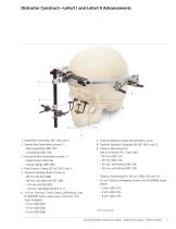
Distractor Construct—LeFort I and LeFort II Advancements 1. Headframe Assembly (390.100) (use 1) 2. Vertical Rod Assemblies (choose 1) – Non-angulating (390.102) – Angulating (390.104) 3. Horizontal Rod Assemblies (choose 1) – Rigid clamps (390.106) – Swivel clamps (390.108) 4. Wire Fixation Clamp (03.307.001) (use 2) 5. Titanium Maxillary Rods (choose 2) – 80 mm (04.307.008) – 80 mm, tall offset (04.307.108) – 110 mm (04.500.000) – 110 mm, tall offset (04.307.111) 6. 1.5 mm Titanium Cortex Screws, self-drilling, with PLUSDRIVE® Screw recess (use a minimum of 6, 3 per footplate) – 5 mm (400.055)...
Open the catalog to page 8
Application of Internal Hardware for LeFort I and LeFort II Procedures 1 Make intraoral incision Make a maxillary vestibular incision. Elevate the periosteum to expose the maxilla. Precaution: Factors to be considered and verified: – Occlusal plane – Planned length of advancement (consider relapse and overcorrection) – Lip closure – Soft tissue coverage – Patient pain due to distractor interference with soft tissue – Access to the screws based on approach 2 Mark osteotomy Mark the approximate site of the osteotomy. 3 Fit maxillary footplate assemblies Instrument 347.964 Combination Bending Pliers...
Open the catalog to page 9
Application of Internal Hardware for LeFort I and LeFort II Procedures 4 Contour maxillary rods Instrument 329.18 Bending Pliers Contour the maxillary rods using the bending pliers so that the rods protrude medial to the lip commissures and in a position that does not irritate the lips. Notes: – Etched lines provide a visual guide to simplify the bending process. Bend the rods along the corresponding etched line to enable them to protrude through the lips parallel to the sagittal plane. – A torsional bend may be necessary to achieve the proper position. – Position the wire fixation clamps on...
Open the catalog to page 10
Application of Internal Hardware for LeFort I and LeFort II Procedures 5 Mark positions of maxillary footplates Instrument 311.005 Screwdriver Handle with Hex Coupling, small Mark the positions of the maxillary footplates before making the osteotomy by inserting two appropriate length screws through each footplate using the 1.5 mm/2.0 mm screwdriver blade. Do not fully tighten the screws. Precautions: – Firmly press the screwdriver blade into the screw recess to ensure retention of the screw on the screwdriver blade. – Take care to avoid nerves, tooth buds and roots, or other critical structures...
Open the catalog to page 11All Depuy Synthes catalogs and technical brochures
 Titanium Sternal Fixation System
34 Pages
 Small Battery Drive II
4 Pages
 Introducing The Variable Angle
12 Pages

Archived catalogs
 MatrixRIB®FixationSystem
86 Pages
 HEALIX ADVANCE
4 Pages
 HEALIX Anchor™ 3.4 mm
2 Pages
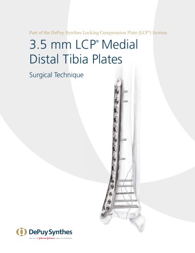 3.5 mm LCP™ Medial
15 Pages
 RADIUS OF CURVATURE
3 Pages
 Building on Success
16 Pages
 2.0 mm LCP® Distal Ulna Plate
20 Pages
 2.4 mm VA LCP™
4 Pages
 Mandible Trauma Solutions
2 Pages
 Power line II
4 Pages
 Concorde
28 Pages
 LCP Intercarpal
31 Pages
 LCS® COMPLETE™
2 Pages
 Synthes TPLO.
8 Pages
 SynFix-LR System
56 Pages
 ATB Anterior Tension Band Plate
32 Pages
 CONDUIT™
15 Pages
 Brochure_FINAL
2 Pages
 DePuy Synthes
81 Pages
 Anspach
3 Pages
 Orthopedic Foot Instruments
32 Pages
 PINNACLE® Hip Solutions
12 Pages
 Corail
24 Pages
 S-ROM® NOILES™
68 Pages
 TRI-LOCK® Product Rationale
12 Pages
 Reclaim Surgical Technique
44 Pages
 Speed
Speed2 Pages
 attune
80 Pages
 HAMMERLOCK® 2
2 Pages
 DePuy Glenoid Solutions
2 Pages
 Trauma Solutions. Elbow
4 Pages
 Polar
Polar4 Pages
 Alveolar Distractor.
4 Pages
 Piezoelectric System
4 Pages
 Air Power Line II
6 Pages
 LCP Clavicle Hook Plate
4 Pages
 TruMatch Pin Guides
16 Pages
 P F N A
8 Pages
 SKILL, DEDICATION,
16 Pages
 Orthopaedics. Overview
20 Pages
 DURALOC
16 Pages
 Marathon Cemented Cup
20 Pages
 REEF Surgical Technique
16 Pages
 MatrixNEURO
8 Pages
 Anspach XMax
4 Pages
 Anspach eMax 2 Plus
4 Pages
 Small Electric Drive
4 Pages
 Air Pen Drive
4 Pages
 Colibri II
4 Pages
 Spine
Spine25 Pages
 Expert Hindfoot Arthrodesis Nail
48 Pages
 LCP Distal Fibula Plates
32 Pages
 TomoFix
60 Pages
 Expert Tibial Nail PROtect
16 Pages
 Expert Tibia Nail
84 Pages
 Sacral Bars
16 Pages
 Pelvic C-Clamp
20 Pages
 Low Profile Pelvic System
16 Pages
 Proximal Femoral (Hook) Plate
24 Pages
 LCP
LCP24 Pages
 PFNA
PFNA112 Pages
 HCS 1.5, 2.4, 3.0
36 Pages
 LCP Wrist Fusion
32 Pages
 LCP Compact Hand
28 Pages
 VA-LCP Elbow
48 Pages
 Distal Radius
44 Pages
 Olecranon
30 Pages
 LCP Hook Plate
28 Pages
 DHP & Olecranon
4 Pages
 LCP S-A
4 Pages
 Epoca
Epoca4 Pages
 Philos
32 Pages
 MultiLoc
68 Pages


- DePuy Synthes bone plate
- Compression plate
- Metallic compression plate
- Locking compression plate
- Titanium compression plate
- Distal compression plate
- Orthopedic surgery instrument kit
- Interbody fusion cage
- Sterilization container
- Instrument sterilization container
- Arthrodesis nail
- Bone substitute
- Metallic intramedullary nail
- Anterior interbody fusion cage
- Femoral stem
- Arthrodesis plate
- Orthopedic surgery bone substitute
- Femoral intramedullary nail
- Metallic arthrodesis plate
- Knee prosthesis