
- Catalogs
- Depuy Synthes
- HCS 1.5, 2.4, 3.0


HCS 1.5, 2.4, 3.0

HCS 1.5, 2.4, 3.0
This technical guide provides instructions for using the HCS 2.4/3.0 countersinkable compression screw in surgical procedures for small bone fractures and osteotomies. It highlights the necessity of training by experienced surgeons for effective application.
The HCS screws are equipped with self-drilling and self-tapping flutes, facilitating surgical techniques and reducing operation time. They are designed for minimally invasive procedures with guided insertion and are available in various thread lengths and materials, such as stainless steel and titanium, to meet diverse surgical requirements.
The screws utilize a lag screw technique with a compression sleeve, involving screw insertion, fracture gap closure with compression, and countersinking without additional compression.
The screws are suitable for fixing intra-articular and extra-articular fractures, non-unions of small bones, arthrodeses of small joints, and bunionectomies. They can be applied to bones like the scaphoid, metacarpals, and tarsals.
Hand – Scaphoid: The procedure includes guide wire insertion, optional trapezium reaming, screw and thread length determination, predrilling, screw insertion, and fragment compression, followed by countersinking.
Foot – Chevron Osteotomy for Hallux Valgus: This involves bunion removal, V-shaped osteotomy, guide wire insertion, screw and thread length determination, predrilling, screw insertion, and osteotomy compression, with similar countersinking as in the hand procedure.
The guide provides detailed information on implants and instruments for HCS 2.4 and 3.0, including optional instruments and setlists.
General guidelines for Synthes instruments' care and maintenance are available online, stressing function control and proper dismantling of multi-part instruments.
The guide alone is insufficient for direct use of the instrument set; professional instruction is recommended.
This document is a technical guide for Synthes HCS 2.4/3.0 mm Headless Compression Screws, detailing specifications, procedures, and instruments required for surgical applications.
The guide covers two sizes of headless compression screws (HCS): 2.4 mm and 3.0 mm, including details on screw lengths, shaft thread lengths, and materials (Stainless Steel and Titanium Alloy). All implants are available sterile packed.
The document outlines steps for inserting and extracting screws, including using a cannulated screwdriver through a compression sleeve, countersinking the screw, and verifying screw position with an image intensifier. It also describes removing protruding bone and using a drill guide with stop for controlled drilling.
A comprehensive list of instruments is provided, including drill bits, screwdriver shafts, handles, compression sleeves, and optional tools like guide wires and trapezium burrs. Each instrument's purpose, such as predrilling or screw extraction, is specified.
The guide emphasizes verifying screw position to avoid distal cortex penetration and provides instructions for setting drilling depth using a measuring device. It also advises using color markings on screwdriver shafts to control countersink depth.
Detailed tables list available screw lengths and corresponding shaft thread lengths for both short and long thread options in the HCS 2.4 mm and 3.0 mm categories.
The document includes setlists for instrument and implant sets for both HCS 2.4 mm and 3.0 mm, specifying additional components required for adaptation between the two sizes.
Catalog excerpts
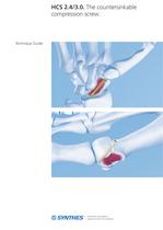
compression screw. Technique Guide
Open the catalog to page 1
Introduction Features and Benefits 2 Surgical Technique Hand - Scaphoid 5 Foot - Chevron Osteotomy for Hallux Valgus 14 Using the Optional Drill Guide with Stop 21 Product Information Implants HCS 2.4 23 Image intensifier control This description alone does not provide sufficient background for direct use of the instrument set. Instruction by a surgeon experienced in handling these nstruments is highly recommended Reprocessing, Care and Maintenance of Synthes Instruments For general guidelines, function control and dismantling of multi-part instruments, please refer to: www.synthes.com/reprocessing...
Open the catalog to page 3
Features and Benefits Tip with self-drilling and selftapping flutes Shorter surgery due to simplified surgical technique Cannulation For minimally invasive technique and guided insertion Head with self-tapping flutes Facilitates countersinking of screw Two different thread lengths of the shaft The optimal implant for every case due to threads available in different lengths P1 P1 Identical pitch of head and shaft threads For controlled closure and compression of the fracture gap Available in steel and titanium All Headless Compression screws from Synthes are available both in stainless implant-grade...
Open the catalog to page 4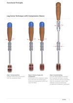
Functional Principle Lag Screw Technique with Compression Sleeve Step 1: Screw insertion nsertion of the screw into the bone with the compression sleeve. Once the tip of the compression sleeve lies on the bone, the fracture gap is closed and compressed by further turn- Once the desired degree of compres- sion is reached, the screw is counter- sunk into the bone with the screwdriver while the compression sleeve is held stationary. During countersinking no additional compression is generated.
Open the catalog to page 5
Indications – Fixation of intra-articular and extra-articular fractures and non-unions of small bones and small bone fragments – Arthrodeses of small joints – Bunionectomies and osteotomies Examples include, but are not limited to scaphoid and other carpal bones, metacarpals, tarsals, metatarsals, patella, ulnar styloid, capitellum, radial head and radial styloid. 4 Synthes HCS 2.4/3.0 Technique Guide
Open the catalog to page 6
Hand - Scaphoid The following simplified surgical technique for a scaphoid fracture serves as example for the use of the HCS 2.4 or 3.0 Insert the guide wire 292.623 Guide Wire 01.1 mm with trocar tip, length 150 mm. Stainless Steel 292.622 Guide Wire 01.1 mm with threaded tip, with trocar, length 1 50 mm. Stainless Steel 312.151 Double Drill Guide 2.0/1.1 O While monitoring with the image intensifier, advance the guide wire through the drill guide into the bone until the thread tip is anchored in the far cortex. Note: Do not forcefully insert the guide wire. This may cause
Open the catalog to page 7
Hand - Scaphoid Option: ream the trapezium 03.226.003 Trapezium Burr, cannulated, for HCS - Headless Compression Screw 03.226.005 Protection Sleeve for HCS - Headless 31 1.430 Handle with Quick Coupling, To facilitate screw insertion, the flank of the trapezium can be removed with the trapezium burr. Slide the trapezium burr with the protection sleeve over the guide wire and carefully ream the trapezium. O Ensure that the trapezium burr does not damage the scaphoid by using image intensification. Note: Do not forcefully insert the trapezium burr since this may damage the guide wire. Synthes HCS...
Open the catalog to page 8
3 Determine screw and thread length Instruments 03.226.002 Direct Measuring Device for HCS – Headless Compression Screw л 2.4/3.0 mm 292.623 Guide Wire л 1.1 mm with trocar tip, length 150 mm, Stainless Steel or 292.622 Guide Wire л 1.1 mm with threaded tip, with trocar, length 150 mm, Stainless Steel Slide the narrow end of the measuring device over the guide wire to the bone. The measurement on the measuring device shows the depth of the guide wire in the bone in millimeters and directly the appropriate screw length. If the screw is to be countersunk below the surface of the bone, subtract...
Open the catalog to page 9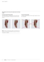
Hand - Scaphoid The position of the fracture line determines the thread Correctly selected thread length The shaft thread lies completely within the proximal frag- ment during compression. Fragments can hence be com- Incorrect thread length The shaft thread lies over the fracture gap. Fragments cannot Note: If there is no good bone quality in the distal part of the bone, the distal screw thread can strip-out if too much Synthes HCS 2.4/3.0 Technique Guide
Open the catalog to page 10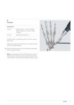
4 Predrilling Instruments 310.221 Drill Bit л 2.0/1.15 mm, cannulated, length 150/48 mm, 3-flute, for Quick Coupling 312.151 Double Drill Guide 2.0/1.1 Predrilling makes it substantially easier to insert the screw in dense bone. Slide the drill guide with the drill bit over the guide wire and pre-drill to the desired depth. Remove the drill guide and verify the effective drilling depth with the image intensifier. Note: Do not drill beyond the tip of the guide wire. Slowly pull the drill bit straight out while running the power tool in “forward mode” to ensure that the guide wire stays in place....
Open the catalog to page 11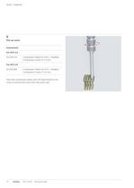
Hand – Scaphoid 5 Pick up screw Instruments For HCS 2.4 03.226.016 Compression Sleeve for HCS – Headless Compression Screw л 2.4 mm For HCS 3.0 03.226.000 Compression Sleeve for HCS – Headless Compression Screw л 3.0 mm Twist the compression sleeve over the head thread of the screw to remove the screw from the screw rack. 10 Synthes HCS 2.4/3.0 Technique Guide
Open the catalog to page 12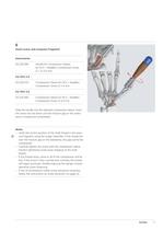
6 Insert screw and compress fragment Instruments 03.226.006 Handle for Compression Sleeve, for HCS – Headless Compression Screw л 1.5–3.0 mm For HCS 2.4 03.226.016 Compression Sleeve for HCS – Headless Compression Screw л 2.4 mm For HCS 3.0 03.226.000 Compression Sleeve for HCS – Headless Compression Screw л 3.0 mm Slide the handle into the selected compression sleeve. Insert the screw into the bone until the fracture gap or the osteotomy is closed and compressed. Notes – Verify the correct position of the shaft thread in the proximal fragment using the image intensifier. If the thread lies over...
Open the catalog to page 13All Depuy Synthes catalogs and technical brochures
 Titanium Sternal Fixation System
34 Pages
 Small Battery Drive II
4 Pages
 Introducing The Variable Angle
12 Pages

Archived catalogs
 MatrixRIB®FixationSystem
86 Pages
 HEALIX ADVANCE
4 Pages
 HEALIX Anchor™ 3.4 mm
2 Pages
 3.5 mm LCP™ Medial
15 Pages
 RADIUS OF CURVATURE
3 Pages
 Building on Success
16 Pages
 2.0 mm LCP® Distal Ulna Plate
20 Pages
 2.4 mm VA LCP™
4 Pages
 Mandible Trauma Solutions
2 Pages
 Power line II
4 Pages
 Concorde
28 Pages
 LCP Intercarpal
31 Pages
 LCS® COMPLETE™
2 Pages
 Synthes TPLO.
8 Pages
 SynFix-LR System
56 Pages
 ATB Anterior Tension Band Plate
32 Pages
 CONDUIT™
15 Pages
 Brochure_FINAL
2 Pages
 DePuy Synthes
81 Pages
 Anspach
3 Pages
 Orthopedic Foot Instruments
32 Pages
 PINNACLE® Hip Solutions
12 Pages
 Corail
24 Pages
 S-ROM® NOILES™
68 Pages
 TRI-LOCK® Product Rationale
12 Pages
 Reclaim Surgical Technique
44 Pages
 Speed
Speed2 Pages
 attune
80 Pages
 HAMMERLOCK® 2
2 Pages
 DePuy Glenoid Solutions
2 Pages
 Trauma Solutions. Elbow
4 Pages
 Polar
Polar4 Pages
 Alveolar Distractor.
4 Pages
 Piezoelectric System
4 Pages
 Air Power Line II
6 Pages
 LCP Clavicle Hook Plate
4 Pages
 TruMatch Pin Guides
16 Pages
 P F N A
8 Pages
 SKILL, DEDICATION,
16 Pages
 Orthopaedics. Overview
20 Pages
 DURALOC
16 Pages
 Marathon Cemented Cup
20 Pages
 REEF Surgical Technique
16 Pages
 MatrixNEURO
8 Pages
 Anspach XMax
4 Pages
 Anspach eMax 2 Plus
4 Pages
 Small Electric Drive
4 Pages
 Air Pen Drive
4 Pages
 Colibri II
4 Pages
 Spine
Spine25 Pages
 Expert Hindfoot Arthrodesis Nail
48 Pages
 LCP Distal Fibula Plates
32 Pages
 TomoFix
60 Pages
 Expert Tibial Nail PROtect
16 Pages
 Expert Tibia Nail
84 Pages
 Sacral Bars
16 Pages
 Pelvic C-Clamp
20 Pages
 Low Profile Pelvic System
16 Pages
 Proximal Femoral (Hook) Plate
24 Pages
 LCP
LCP24 Pages
 PFNA
PFNA112 Pages
 LCP Wrist Fusion
32 Pages
 LCP Compact Hand
28 Pages
 VA-LCP Elbow
48 Pages
 Distal Radius
44 Pages
 Olecranon
30 Pages
 LCP Hook Plate
28 Pages
 DHP & Olecranon
4 Pages
 LCP S-A
4 Pages
 Epoca
Epoca4 Pages
 Philos
32 Pages
 MultiLoc
68 Pages




- DePuy Synthes bone plate
- Compression plate
- Metallic compression plate
- Locking compression plate
- Titanium compression plate
- Orthopedic surgery instrument kit
- Distal compression plate
- Interbody fusion cage
- Sterilization container
- Instrument sterilization container
- Arthrodesis nail
- Bone substitute
- Metallic intramedullary nail
- Femoral stem
- Anterior interbody fusion cage
- Arthrodesis plate
- Orthopedic surgery bone substitute
- Femoral intramedullary nail
- Knee prosthesis
- Metallic arthrodesis plate