- Catalogs
- Depuy Synthes
- Headless Compression Screws 4.5 & 6.5
Headless Compression Screws 4.5 & 6.5

Headless Compression Screws 4.5 & 6.5
This document provides comprehensive instructions for using the HCS 4.5/6.5 countersinkable compression screws, designed for surgical procedures involving fractures, osteoarthritis, or deformities of small to large bones. These screws are available in stainless steel and titanium alloy, featuring self-drilling tips, reverse-cutting flutes, and identical pitch of head and shaft threads for controlled compression.
The surgical procedure includes several key steps:
- Guide Wire Insertion: Insert the guide wire through the drill sleeve assembly to the bone, ensuring it is anchored in the far cortex.
- Determine Screw and Thread Length: Measure the appropriate screw length based on the guide wire depth.
- Predrilling: Use a cannulated drill bit to predrill the bone for easier screw insertion.
- Pick Up and Insert Screw: Use screw forceps to pick up and insert the screw into the bone, compressing the fracture gap.
- Countersink Screw: Use a cannulated screwdriver to countersink the screw, ensuring it does not project from the bone surface.
The HCS 4.5 is indicated for fractures or deformities in bones such as the calcaneus, talus, metatarsus, distal and proximal tibia, distal femur, and proximal humerus. The HCS 6.5 is similarly indicated but excludes the proximal humerus.
The document details the specifications of the HCS 4.5 and 6.5 screws, including available lengths and materials. It also lists the necessary instruments for the surgical procedure, such as guide wires, protection sleeves, drill sleeves, and screwdrivers.
Instructions for screw removal involve using a cannulated screwdriver and compression sleeve to extract the screw by turning counterclockwise.
General guidelines for the care and maintenance of Synthes instruments are available at www.synthes.com/reprocessing. It is recommended that users receive instruction from experienced surgeons before using the instrument set.
- HCS 4.5: Available in long thread with screw lengths ranging from 30 mm to 110 mm. Shaft thread length is approximately 40% of the screw length. Material options include Stainless Steel (X=2) and TAN (X=4). All screws are available sterile packed.
- HCS 6.5: Available in both short and long thread options. Short thread screws have a consistent shaft thread length of 16 mm, while long thread screws have a shaft thread length of 32 mm. Screw lengths range from 30 mm to 130 mm. Material options include Stainless Steel (X=2) and TAN (X=4). All screws are available sterile packed.
- Standard Instruments for HCS 4.5: Include guide wires, protection sleeves, drill sleeves, trocars, direct measuring devices, drill bits, compression sleeves, screwdrivers, screw forceps, and cleaning stylets.
- Optional Instruments for HCS 4.5: Include additional guide wires, taps, T-handles, cleaning brushes, and screwdriver shafts.
- Standard Instruments for HCS 6.5: Include guide wires, protection sleeves, drill sleeves, trocars, direct measuring devices, drill bits, compression sleeves, screwdrivers, screw forceps, and cleaning stylets.
- Optional Instruments for HCS 6.5: Include taps, additional guide wires, drill bits, cleaning brushes, and screwdriver shafts.
All screws are available in sterile packaging, with certain sizes only available in this format.
Synthes GmbH, Eimattstrasse 3, CH-4436 Oberdorf. All technique guides are available as PDF files at www.synthes.com/lit.
Catalog excerpts

compression screw.
Open the catalog to page 1
Surgical Technique Surgical Technique for HCS 4.5 and 6.5* 5 Product Information Implants - HCS 4.5 16 Image intensifier control This description alone does not provide sufficient background for direct use of the instrument set. Instruction by a surgeon experienced in handling these nstruments is highly recommended Reprocessing, Care and Maintenance of Synthes Instruments For general guidelines, function control and dismantling of multipart instruments, please refer to: www.synthes.com/reprocessing
Open the catalog to page 3
compression screw. Shorter surgery due to simplified surgi- Reverse-cutting flutes Facilitate screw removal and prevent potential breaking of implant For minimally invasive technique and guided insertion Cutting flutes Facilitate countersinking of the screw All headless compression screws from Synthes are available in stainless implant-grade steel Identical pitch of head and shaft threads Two different thread lengths The optimal implant for every case due to threads available in different lengths
Open the catalog to page 4
Functional principle: Lag screw technique with compression sleeve Screw insertion nsert the screw into the bone with Once the tip of the compression sleeve lies on the bone, the fracture gap is closed and compressed by turning the Once the desired degree of compres- sion is reached, the screw is countersunk into the bone with the screwdriver while the compression sleeve is held stationary. During countersinking, no additional compression is generated.
Open the catalog to page 5
Indications HCS 4.5 Fracture, osteoarthritis, or deformity of small to large bones. Examples: − Calcaneus − Talus − Metatarsus − Distal and proximal tibia − Distal femur − Proximal humerus HCS 6.5 Fracture, osteoarthritis, or deformity of small to large bones. Examples: − Calcaneus − Talus − Distal and proximal tibia − Distal femur 4 Synthes HCS 4.5/6.5 Instructions for Use
Open the catalog to page 6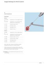
Insert the guide wire Guide Wire 0 1.6 mm, length 220 mm Guide Wire 0 1.6 mm with trocar tip, length 220 mm. Stainless Steel Guide Wire 0 2.8 mm, length 300 mm Guide Wire 0 2.8 mm with trocar tip, length 300 mm. Stainless Steel After a stab incision, advance the drill sleeve assembly through the soft tissues until it reaches the bone. While monitoring with the image intensifier, advance the guide wire through the drill sleeve assembly until the thread tip is anchored in the far cortex of the bone. C Warning: Do not forcefully insert the guide wire as it may cause bending.
Open the catalog to page 7
Determine screw and thread length 03.226.030 Direct Measuring Device for HCS 4.5 03.227.030 Direct Measuring Device for HCS 6.5 Remove the drill sleeve. Slide the narrow end of the measur- ng device through the protection sleeve and over the guide wire until it reaches the bone. The measurement on the measuring device shows the depth in millimeters of the guide wire in the bone. This depth indi- cates the appropriate screw length. Important: Only use the guide wire in its prescribed length to ensure correct measurement. If the screw is to be counter- sunk below the surface of the bone, subtract...
Open the catalog to page 8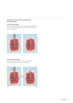
The position of the fracture line determines Correct thread length The shaft thread lies below the fracture gap and completely within the distal fragment during compression. Fragments Incorrect thread length The shaft thread lies above the fracture gap or the osteotomy. Fragments cannot be compressed.
Open the catalog to page 9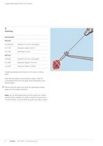
Surgical Technique for HCS 4.5 and 6.5 3 Predrilling Instruments HCS 4.5 03.226.039 Drill Bit л 3.2 mm, cannulated 312.770 Protection Sleeve 9.5/7.0 312.760 Drill Sleeve 7.0/3.2 HCS 6.5 310.630 Drill Bit л 5.0 mm, cannulated 312.090 Protection Sleeve 15.5/13.0 312.050 Protection Sleeve 12.0/8.5 Predrilling facilitates the insertion of the screw in dense bone. Insert the drill sleeve in the protection sleeve. Slide the cannulated drill bit over the guide wire and predrill to the desired depth. Remove the drill sleeve and verify the appropriate drilling depth with the image intensifier. Note: Do...
Open the catalog to page 10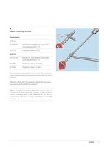
Option: Predrilling for head 03.226.042 Drill Bit for predrilling for screw head, 03.227.042 Drill Bit for predrilling for screw head, The corticalis can be predrilled with the drill bit to facilitate head insertion in dense bone and to prevent the bone from Slide the drill bit with the protection sleeve over the guide wire and carefully predrill the corticalis. Note: The depth of predrilling depends on the inclination of the guide wire to the bone. It is necessary to predrill only to the first marking in cases where angulation is ± 90°. An an- gulation of ± 45° requires a deeper predrilling...
Open the catalog to page 11
319.970 Screw Forceps, self-holding, length 85 mm 319.970 Screw Forceps, self-holding, length 85 mm To remove a screw from the screw rack, pick it up with the screw forceps and twist the compression sleeve over the Attention: Do not remove the screw with the compression sleeve directly from the screw rack. The screw rack could be Insert screw and compress fragments 03.226.037 Handle for Compression Sleeve for HCS 4.5 03.226.038 Attachment for Compression Sleeve
Open the catalog to page 12
03.227.037 Handle for Compression Sleeve for 03.227.038 Attachment for Compression Sleeve Slide the compression sleeve handle into the compression sleeve. Insert the screw assembly over the guide wire. Insert the screw into the bone by turning the compression sleeve until the fracture gap or the osteotomy is closed and com- Option: Screw insertion can also be performed with the use of a power drill. Slide the attachment for compression sleeve into the compression sleeve and connect it to the power drill. Warning: Insert the screw into the bone and stop before the compression sleeve touches the...
Open the catalog to page 13
Surgical Technique for HCS 4.5 and 6.5 Optional instruments for use with 4.5 mm screws 03.226.034 Sleeve for Compression Sleeve for HCS – Headless Compression Screw л 4.5 mm for use with 6.5 mm screws 03.227.034 Sleeve for Compression Sleeve for HCS – Headless Compression Screw л 6.5 mm In osteoporotic bone, an additional sleeve should be placed over the compression sleeve before compressing the fracture or osteotomy to prevent the compression sleeve from piercing the cortex. Notes – Verify the correct position of the shaft thread in the distal fragment using the image intensifier. If the thread...
Open the catalog to page 14All Depuy Synthes catalogs and technical brochures
 Titanium Sternal Fixation System
34 Pages
 Small Battery Drive II
4 Pages
 Introducing The Variable Angle
12 Pages

Archived catalogs
 MatrixRIB®FixationSystem
86 Pages
 HEALIX ADVANCE
4 Pages
 HEALIX Anchor™ 3.4 mm
2 Pages
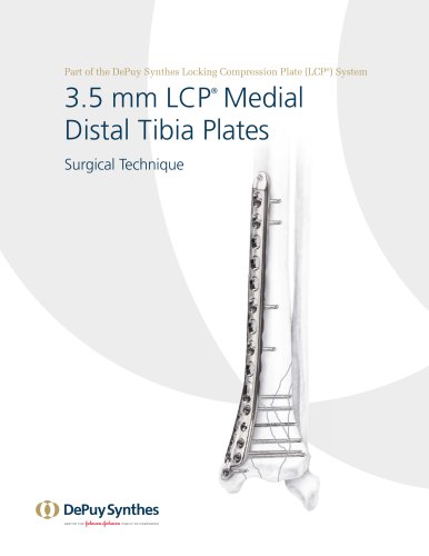 3.5 mm LCP™ Medial
15 Pages
 RADIUS OF CURVATURE
3 Pages
 Building on Success
16 Pages
 2.0 mm LCP® Distal Ulna Plate
20 Pages
 2.4 mm VA LCP™
4 Pages
 Mandible Trauma Solutions
2 Pages
 Power line II
4 Pages
 Concorde
28 Pages
 LCP Intercarpal
31 Pages
 LCS® COMPLETE™
2 Pages
 Synthes TPLO.
8 Pages
 SynFix-LR System
56 Pages
 ATB Anterior Tension Band Plate
32 Pages
 CONDUIT™
15 Pages
 Brochure_FINAL
2 Pages
 DePuy Synthes
81 Pages
 Anspach
3 Pages
 Orthopedic Foot Instruments
32 Pages
 PINNACLE® Hip Solutions
12 Pages
 Corail
24 Pages
 S-ROM® NOILES™
68 Pages
 TRI-LOCK® Product Rationale
12 Pages
 Reclaim Surgical Technique
44 Pages
 Speed
Speed2 Pages
 attune
80 Pages
 HAMMERLOCK® 2
2 Pages
 DePuy Glenoid Solutions
2 Pages
 Trauma Solutions. Elbow
4 Pages
 Polar
Polar4 Pages
 Alveolar Distractor.
4 Pages
 Piezoelectric System
4 Pages
 Air Power Line II
6 Pages
 LCP Clavicle Hook Plate
4 Pages
 TruMatch Pin Guides
16 Pages
 P F N A
8 Pages
 SKILL, DEDICATION,
16 Pages
 Orthopaedics. Overview
20 Pages
 DURALOC
16 Pages
 Marathon Cemented Cup
20 Pages
 REEF Surgical Technique
16 Pages
 MatrixNEURO
8 Pages
 Anspach XMax
4 Pages
 Anspach eMax 2 Plus
4 Pages
 Small Electric Drive
4 Pages
 Air Pen Drive
4 Pages
 Colibri II
4 Pages
 Spine
Spine25 Pages
 Expert Hindfoot Arthrodesis Nail
48 Pages
 LCP Distal Fibula Plates
32 Pages
 TomoFix
60 Pages
 Expert Tibial Nail PROtect
16 Pages
 Expert Tibia Nail
84 Pages
 Sacral Bars
16 Pages
 Pelvic C-Clamp
20 Pages
 Low Profile Pelvic System
16 Pages
 Proximal Femoral (Hook) Plate
24 Pages
 LCP
LCP24 Pages
 PFNA
PFNA112 Pages
 HCS 1.5, 2.4, 3.0
36 Pages
 LCP Wrist Fusion
32 Pages
 LCP Compact Hand
28 Pages
 VA-LCP Elbow
48 Pages
 Distal Radius
44 Pages
 Olecranon
30 Pages
 LCP Hook Plate
28 Pages
 DHP & Olecranon
4 Pages
 LCP S-A
4 Pages
 Epoca
Epoca4 Pages
 Philos
32 Pages
 MultiLoc
68 Pages


- DePuy Synthes bone plate
- Compression plate
- Metallic compression plate
- Locking compression plate
- Titanium compression plate
- Distal compression plate
- Orthopedic surgery instrument kit
- Interbody fusion cage
- Sterilization container
- Instrument sterilization container
- Arthrodesis nail
- Bone substitute
- Metallic intramedullary nail
- Femoral stem
- Anterior interbody fusion cage
- Arthrodesis plate
- Orthopedic surgery bone substitute
- Femoral intramedullary nail
- Metallic arthrodesis plate
- Knee prosthesis