- Catalogs
- Depuy Synthes
- LCP Distal Tibia Plate - Low Bend
LCP Distal Tibia Plate - Low Bend
LCP Distal Tibia Plate - Low Bend
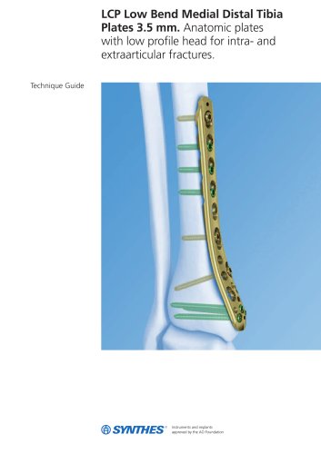
The document is a technical guide for the LCP Low Bend Medial Distal Tibia Plates 3.5 mm, designed for treating intra- and extra-articular fractures. These plates are part of the Synthes Small Fragment LCP system, which integrates locking screw technology with conventional plating techniques.
The guide outlines the AO principles applied to these plates: anatomic reduction, stable fixation, preservation of blood supply, and early mobilization. These principles are crucial for effective internal fixation and optimal bone healing.
The plates are intended for complex intra- and extra-articular fractures and osteotomies of the distal tibia.
Preoperative planning involves radiographic assessment and determining the appropriate plate length and instruments. The patient is positioned supine on a radiolucent table.
Fracture fragments are reduced using methods such as Kirschner wires and lag screws, with image intensification confirming reduction.
The plate can be inserted percutaneously or through an open approach. Proper alignment is checked using fluoroscopy, and the plate is temporarily fixed before screw insertion.
Distal screws are inserted first, using a combination of locking and cortex screws. Detailed steps are provided for inserting screws in both distal and shaft combi-holes.
All screws must be unlocked from the plate before removal to prevent plate rotation. An extraction screw with a left-handed thread can be used if screws are stuck.
The plates feature a low-profile head, rounded edges, and a limited-contact shaft profile to minimize soft tissue irritation. They are available in stainless steel or titanium.
The guide emphasizes the importance of instruction by an experienced surgeon and provides a link for reprocessing and maintenance guidelines.
This document provides detailed specifications and guidelines for the 3.5 mm LCP Low Bend Medial Distal Tibia Plate Implant Sets, available in both stainless steel and titanium. These plates are designed for use in orthopedic surgeries involving the distal tibia.
- The implant sets include trays for both stainless steel (01.112.063) and titanium (01.112.062) plates, designed for the Vario Case without lids.
- Plates are available for both right and left tibia, with varying hole counts and lengths ranging from 109 mm to 239 mm.
- All plates can be ordered sterile by adding an 'S' suffix to the article number.
- 2.7 mm cortex screws are used in distal locking holes to compress the plate to the bone.
- 3.5 mm cortex screws are used in the DCU portion of combi-holes for compression or axial compression.
- 3.5 mm locking screws provide a fixed-angle construct with a self-tapping tip.
- 4.0 mm cancellous bone screws are used for compression in the DCU portion of combi-holes.
- Various instruments are listed, including Kirschner Wires, LCP Drill Bits, Screwdrivers, Depth Gauges, and Torque Limiters, all designed to facilitate the surgical procedure.
- Synthes GmbH, located at Eimattstrasse 3, CH-4436 Oberdorf, is the manufacturer of these implant sets.
- All technique guides are available as PDF files on the Synthes website.
Catalog excerpts

LCP Low Bend Medial Distal Tibia Plates 3.5 mm. Anatomic plates with low profile head for intra- and extraarticular fractures. Technique Guide
Open the catalog to page 1
Introduction LCP Low Bend Medial Distal Tibia Plates 3.5 mm 2 Surgical Technique Preparation 6 Product Information Set Lists 17 Image intensifier control This description alone does not provide sufficient background for direct use of the instrument set. Instruction by a surgeon experienced in handling these nstrument is highly recommended Reprocessing, Care and Maintenance of Synthes Instruments For general guidelines, function control and dismantling of multipart instruments please refer to: www.synthes.com/reprocessing
Open the catalog to page 3
LCP Low Bend Medial Distal Tibia Plates 3.5 mm The LCP Low Bend Medial Distal Tibia Plate 3.5 mm is part of the Synthes Small Fragment LCP system that merges locking screw technology with conventional plating techniques. The combi-holes in the LCP plate shaft combine a dynamic compression unit (DCU) hole with a locking screw hole. Combi-holes provide the flexibility of axial compression and locking capability throughout the length of the plate shaft. Fixation with the 3.5 mm LCP Low Bend Medial Distal Tibia Plate has many similarities to traditional plate fixation methods, with a few important...
Open the catalog to page 4
Plate features – Head of plate is low profile for minimal prominence on medial malleolus – 3.5 mm cortex and 4.0 mm cancellous bone screws sit flush with plate in the nonlocking portion of distal combiholes to minimize screw prominence – Rounded edges to minimize soft tissue irritation – Limited-contact shaft profile – Available in stainless steel or titanium Combi-holes in the shaft and head accept the following: – 3.5 mm cortex screws – 3.5 mm locking screws – 4.0 mm cancellous bone screws Three distal locking screws diverge across subchondral bone and are parallel to joint Six round locking...
Open the catalog to page 5
AO Principles In 1958, the AO formulated four basic principles, which have become the guidelines for internal fixation.1,2 Those principles, as applied to the 3.5 mm LCP Low Bend Medial Distal Tibia Plate, are: Anatomic reduction Precontoured plate assists reduction of metaphysis to diaphysis and facilitates restoration of the articular surface by exact screw placement. Stable fixation Locking screws create a fixed-angle construct, providing angular stability. Preservation of blood supply Tapered end allows submuscular plate insertion, preserving tissue viability. Limited-contact plate design...
Open the catalog to page 6
Indications The Synthes LCP Low Bend Medial Distal Tibia Plates are intended for fixation of complex intra- and extra-articular fractures and osteotomies of the distal tibia, as a part of the Synthes Small Fragment LCP System. Synthes 5
Open the catalog to page 7
Complete the preoperative radiographic assessment and prepare the preoperative plan. Determine plate length and Position the patient supine on a radiolucent operating table. 3.5 mm LCP Low Bend Medial Distal Tibia Plates set 01.1 12.062 Tray for LCP Medial Distal Tibial Plate 3.5, low bend (TAN), for Vario Case, without Lid, with Contents 01.1 12.063 Tray for LCP Medial Distal Tibial Plate 3.5, low bend (Stainless Steel), for Vario Case, without Lid, with Contents Modular small fragment instrument trays* 68.122.013 Modular Small Fragment Basic Instrument Tray 68.122.015 Modular Small Fragment...
Open the catalog to page 8
Reduction Reduce articular surface Approach An open or a percutaneous approach may be used depending on the fracture. Reduction Technique tip: Application of an external fixator or large distractor may facilitate visualization and reduction of the joint. Reduce the fracture fragments and confirm reduction using image intensification. Methods of stabilizing reduction include the following: – Independent Kirschner wires – K-wires through the plate – Independent lag screws – Lag screws through the plate – Locking screws through the plate Locking screws do not provide interfragment compression; therefore,...
Open the catalog to page 9
Plate Insertion Insert plate Percutaneous insertion For a percutaneous approach, make an incision to access the medial malleolus and slide the plate under the soft tissue. Technique tip: Thread a bending pin or LCP drill guide into one of the distal holes as a handle for percutaneous inser- Open insertion Open the area as necessary to expose the joint. Carefully push the plate under the soft tissue for placement on the Center the plate on the medial malleolus. Important: When choosing a percutaneous approach take care not to damage the saphenous nerve or saphenous vein. Saphenous vein (blue)...
Open the catalog to page 10
2 Position plate and fix provisionally After plate insertion, check alignment on the bone using fluoroscopy. Make any adjustments before inserting screws. Note: This locking plate is precontoured to fit the medial distal tibia. If the plate contour is changed, it is important to check the position of the screws relative to the joint, using the screw placement verification technique. Optional instrument 324.024 Instrument for temporary reduction The plate may be temporarily held in place using any of the following options: – Instrument for temporary reduction (push-pull reduction device) – 4.0...
Open the catalog to page 11
Plate Insertion Optional technique: Screw placement verification with threaded tip, length 1 50/5 mm 310.284 LCP Drill Bit 0 2.8 mm with Stop, 323.027 LCP Drill Sleeve 3.5, for Drill Bits 0 2.8 mm 323.055 Centering Sleeve for Kirschner Wire 323.060 PHILOS Direct Measuring Device Since the direction of the locking screw depends on the con- tour of the plate, final screw position may be verified with a K-wire before insertion. This becomes especially important when the plate has been manually contoured or applied near Synthes LCP Low Bend Medial Distal Tibia Plates 3.5 mm Technique Guide
Open the catalog to page 12
Thread a 3.5 mm LCP drill sleeve into the desired locking hole and insert the 1.6 mm centering sleeve for Kirschner wire into the drill guide. nsert a 1.6 mm threaded K-wire through the centering sleeve and drill to the desired depth. O Verify K-wire placement under image intensification to deter- mine if final screw placement will be acceptable. Important: The K-wire position represents the final position of the locking screw. Confirm that the K-wire does not enter
Open the catalog to page 13All Depuy Synthes catalogs and technical brochures
 Titanium Sternal Fixation System
34 Pages
 Small Battery Drive II
4 Pages
 Introducing The Variable Angle
12 Pages

Archived catalogs
 MatrixRIB®FixationSystem
86 Pages
 HEALIX ADVANCE
4 Pages
 HEALIX Anchor™ 3.4 mm
2 Pages
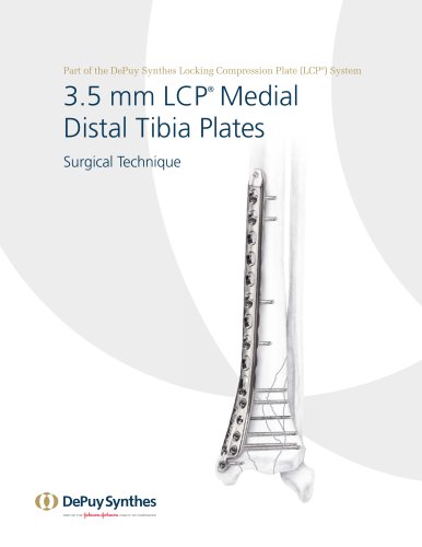 3.5 mm LCP™ Medial
15 Pages
 RADIUS OF CURVATURE
3 Pages
 Building on Success
16 Pages
 2.0 mm LCP® Distal Ulna Plate
20 Pages
 2.4 mm VA LCP™
4 Pages
 Mandible Trauma Solutions
2 Pages
 Power line II
4 Pages
 Concorde
28 Pages
 LCP Intercarpal
31 Pages
 LCS® COMPLETE™
2 Pages
 Synthes TPLO.
8 Pages
 SynFix-LR System
56 Pages
 ATB Anterior Tension Band Plate
32 Pages
 CONDUIT™
15 Pages
 Brochure_FINAL
2 Pages
 DePuy Synthes
81 Pages
 Anspach
3 Pages
 Orthopedic Foot Instruments
32 Pages
 PINNACLE® Hip Solutions
12 Pages
 Corail
24 Pages
 S-ROM® NOILES™
68 Pages
 TRI-LOCK® Product Rationale
12 Pages
 Reclaim Surgical Technique
44 Pages
 Speed
Speed2 Pages
 attune
80 Pages
 HAMMERLOCK® 2
2 Pages
 DePuy Glenoid Solutions
2 Pages
 Trauma Solutions. Elbow
4 Pages
 Polar
Polar4 Pages
 Alveolar Distractor.
4 Pages
 Piezoelectric System
4 Pages
 Air Power Line II
6 Pages
 LCP Clavicle Hook Plate
4 Pages
 TruMatch Pin Guides
16 Pages
 P F N A
8 Pages
 SKILL, DEDICATION,
16 Pages
 Orthopaedics. Overview
20 Pages
 DURALOC
16 Pages
 Marathon Cemented Cup
20 Pages
 REEF Surgical Technique
16 Pages
 MatrixNEURO
8 Pages
 Anspach XMax
4 Pages
 Anspach eMax 2 Plus
4 Pages
 Small Electric Drive
4 Pages
 Air Pen Drive
4 Pages
 Colibri II
4 Pages
 Spine
Spine25 Pages
 Expert Hindfoot Arthrodesis Nail
48 Pages
 LCP Distal Fibula Plates
32 Pages
 TomoFix
60 Pages
 Expert Tibial Nail PROtect
16 Pages
 Expert Tibia Nail
84 Pages
 Sacral Bars
16 Pages
 Pelvic C-Clamp
20 Pages
 Low Profile Pelvic System
16 Pages
 Proximal Femoral (Hook) Plate
24 Pages
 LCP
LCP24 Pages
 PFNA
PFNA112 Pages
 HCS 1.5, 2.4, 3.0
36 Pages
 LCP Wrist Fusion
32 Pages
 LCP Compact Hand
28 Pages
 VA-LCP Elbow
48 Pages
 Distal Radius
44 Pages
 Olecranon
30 Pages
 LCP Hook Plate
28 Pages
 DHP & Olecranon
4 Pages
 LCP S-A
4 Pages
 Epoca
Epoca4 Pages
 Philos
32 Pages
 MultiLoc
68 Pages


- DePuy Synthes bone plate
- Compression plate
- Metallic compression plate
- Locking compression plate
- Titanium compression plate
- Distal compression plate
- Orthopedic surgery instrument kit
- Interbody fusion cage
- Sterilization container
- Instrument sterilization container
- Arthrodesis nail
- Bone substitute
- Metallic intramedullary nail
- Anterior interbody fusion cage
- Femoral stem
- Arthrodesis plate
- Orthopedic surgery bone substitute
- Femoral intramedullary nail
- Suture anchor
- Knee prosthesis