LCP

LCP
This document is a technique guide for the DHS Blade, designed for use in osteoporotic bone. It emphasizes the importance of instruction by an experienced surgeon for proper application.
Features and Benefits
The DHS Blade offers increased rotational stability, better anchorage in the femoral head, and a larger support surface compared to conventional DHS Screws. These features reduce the risk of cut-out and improve performance in osteoporotic bone.
Indications and Contraindications
Indications include pertrochanteric fractures (31-A1, 31-A2), intertrochanteric fractures (31-A3), and basilar neck fractures (31-B). Contraindications include subtrochanteric fractures, high incidence of sepsis, malignant tumors, material sensitivity, and compromised vascularity.
Clinical Cases
The DHS Blade is recommended for osteoporotic patients, while the DHS Screw is suggested for those with good bone quality. Correct placement of the screw or blade is crucial to prevent cut-out.
Surgical Technique
The guide details the steps for implantation, including preoperative planning, insertion of guide wire, determining blade length, drilling, inserting the DHS Blade, orienting and fixing the DHS plate, and locking the implant. It also covers implant removal procedures.
Product Information
The DHS Blade is available in various lengths and is compatible with both conventional and LCP DHS plates. It is only available sterile packed.
Instruments and Sets
A list of instruments required for the procedure is provided, along with information on available implant and instrument sets.
Bibliography
The document references studies and articles that support the use and benefits of the DHS Blade in treating specific fracture types.
Catalog excerpts
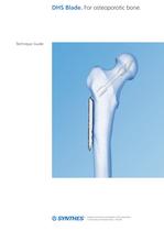
DHS Blade. For osteoporotic bone. Technique Guide ^^^^MOriginal Instruments and Implants of the Association O MMWM llCO for the Study of Internal Fixation-AO ASIF
Open the catalog to page 1
Introduction Features and Benefits 2 Surgical Technique Implantation 6 Product Information DHS Blade 15 O Image intensifier control This description is not sufficient for immediate application of the instrumentation. Instruction by a surgeon experienced in handling this instrumentation is highly recommended.
Open the catalog to page 3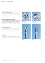
0X6.000.686_AA.qxp:0X6.000.686_AA 10.12.2008 7:55 Uhr Seite 2 Features and Benefits Increased rotational stability The shape of the blade leads to improved rotational stability of the femoral head-neck fragment, which is vital for reducing the risk of cut-out, delayed union and varus angulation in unstable trochanteric fractures. 1 Better anchorage in the femoral head The specially designed tip of the blade allows for compaction of the bone when the blade is inserted. This compaction leads to improved anchorage of the implant in the femoral head, which is beneficial especially in osteoporotic...
Open the catalog to page 4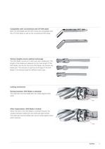
0X6.000.686_AA.qxp:0X6.000.686_AA 10.12.2008 7:55 Uhr Seite 3 Compatible with conventional and LCP DHS plate Both the DHS Blade and the DHS Screw are compatible with the LCP DHS plate as well as the conventional DHS plate. Various lengths ensure optimal anchorage The DHS Blade consists of a shaft part and a blade part. The length of the blade part depends on the total length of the DHS Blade: the shorter the entire DHS Blade, the shorter the blade part. This ensures an optimal anchorage of the DHS Blade in the femoral head for different bone sizes. Locking mechanism During insertion: DHS Blade...
Open the catalog to page 5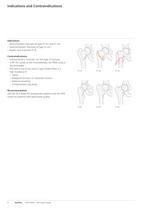
0X6.000.686_AA.qxp:0X6.000.686_AA 10.12.2008 7:55 Uhr Seite 4 Indications and Contraindications Indications – Pertrochanteric fractures of type 31-A1 and 31-A2 – Intertrochanteric fractures of type 31-A3 – Basilar neck fractures 31-B Contraindications – Subtrochanteric fractures: for this type of fracture, a 95º DCS plate or the intramedullary nail PFNA Long is recommended. – The DHS is not to be used in cases where there is a high incidence of: – Sepsis – Malignant primary or metastatic tumors – Material sensitivity – Compromised vascularity 31-A1 31-A2 31-A3 31-B1 31-B2 31-B3 Recommendation...
Open the catalog to page 6
0X6.000.686_AA.qxp:0X6.000.686_AA 10.12.2008 7:55 Uhr Seite 5 Clinical Cases Pertrochanteric fractures Special surgical considerations: Implant of choice Recent metanalysis has shown that the DHS tends to be statistically superior to intramedullary devices for trochanteric fractures.3,4 Further studies are required to determine whether different types of intramedullary nails produce similar results, or whether intramedullary nails are advantageous for certain fracture types (e.g. subtrochanteric fractures).4 Prevention of cut-out: correct placement of the screw The correct placement of the DHS...
Open the catalog to page 7
0X6.000.686_AA.qxp:0X6.000.686_AA 10.12.2008 7:55 Uhr Implantation 1 Preoperative planning The size and angle of the plate as well as the length of the DHS Blade can be determined preoperatively by using the DHS Goniometer (Art. No. 034.000.185). Important: If the DHS Blade is from 65 to 75 mm, a DHS plate with short barrel should be used to allow for sufficient dynamization. 6 Synthes DHS Blade Technique Guide Seite 6
Open the catalog to page 8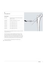
Insert guide wire 292.200 Kirschner Wire 0 2.0 mm with trocar tip, 338.000 DHS/DCS Guide Wire 0 2.5 mm The first stage of the operation remains the same as with the Once the fracture has been stabilized with Kirschner wires and the anteversion wire has been placed in position, place the DHS/DCS guide wire at the desired angle with the correct angled guide. The guide wire should be placed in the middle of the femoral head and extend into the subchondral bone. Check the position of the guide wire in both AP and
Open the catalog to page 9
0X6.000.686_AA.qxp:0X6.000.686_AA 10.12.2008 7:55 Uhr Implantation 3 Determine length of DHS Blade Instrument 338.050 DHS/DCS Direct Measuring Device Read the length of the DHS Blade directly off the guide wire with the measuring device. If the guide wire is inserted into the subchondral bone, remove 5 mm from the measurement. Example: If you read 105 mm on the direct measuring device, the measured length of the implant is 100 mm. 4 Drill for insertion of DHS Blade Instruments 03.224.009 Triple Reamer for DHS Blade, complete Consisting of: 03.224.003 Drill Bit л 6.0/10.5 mm 338.110 DHS Reamer...
Open the catalog to page 10
0X6.000.686_AA.qxp:0X6.000.686_AA 10.12.2008 7:55 Uhr Seite 9 5 Insert DHS Blade Instruments 03.224.001 Insertion Instrument for DHS Blade 03.224.007 Connecting Screw for Insertion of DHS Blade 338.320 DHS/DCS Centering Sleeve Insert the connecting screw into the insertion instrument. Slide the appropriate DHS plate onto the insertion instrument and connect the DHS Blade to the insertion instrument. Warning: Be sure that the DHS Blade is unlocked before you insert it. Mount the centering sleeve onto the insertion instrument and insert the DHS Blade with slight hammering. If excessive hammering...
Open the catalog to page 11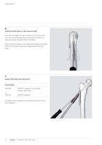
0X6.000.686_AA.qxp:0X6.000.686_AA 10.12.2008 7:55 Uhr Implantation 6 Orient the DHS plate on the femoral shaft Once the DHS Blade has been inserted to the correct position, the centering sleeve can be removed. The plate can then be slid over the shaft of the DHS Blade. Due to the free rotation of the blade part relative to the shaft part, the DHS plate can be easily aligned to the femoral shaft. 7 Impact DHS plate onto the bone Instruments 338.280 or 338.140 DHS/DCS Impactor, for One-Step Insertion Technique DHS/DCS Impactor The plate can be impacted onto the bone with one of the two impactors....
Open the catalog to page 12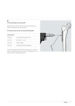
0X6.000.686_AA.qxp:0X6.000.686_AA 10.12.2008 7:55 Uhr Seite 11 8 Fix the DHS plate onto the shaft Remove all the insertion instruments and the guide wire. Then fix the plate to the femoral shaft. A Cortex screws for the conventional DHS plate Instruments 323.460 Universal Drill Guide 4.5 /3.2 310.310 Drill Bit л 3.2 mm 319.010 Depth Gauge 314.150 Screwdriver Shaft, hexagonal Use the drill guide and the drill bit to drill holes in a neutral position through the plate holes. Insert self-tapping 4.5 mm cortex screws of appropriate length. Synthes 11
Open the catalog to page 13All Depuy Synthes catalogs and technical brochures
 Titanium Sternal Fixation System
34 Pages
 Small Battery Drive II
4 Pages
 Introducing The Variable Angle
12 Pages

Archived catalogs
 MatrixRIB®FixationSystem
86 Pages
 HEALIX ADVANCE
4 Pages
 HEALIX Anchor™ 3.4 mm
2 Pages
 3.5 mm LCP™ Medial
15 Pages
 RADIUS OF CURVATURE
3 Pages
 Building on Success
16 Pages
 2.0 mm LCP® Distal Ulna Plate
20 Pages
 2.4 mm VA LCP™
4 Pages
 Mandible Trauma Solutions
2 Pages
 Power line II
4 Pages
 Concorde
28 Pages
 LCP Intercarpal
31 Pages
 LCS® COMPLETE™
2 Pages
 Synthes TPLO.
8 Pages
 SynFix-LR System
56 Pages
 ATB Anterior Tension Band Plate
32 Pages
 CONDUIT™
15 Pages
 Brochure_FINAL
2 Pages
 DePuy Synthes
81 Pages
 Anspach
3 Pages
 Orthopedic Foot Instruments
32 Pages
 PINNACLE® Hip Solutions
12 Pages
 Corail
24 Pages
 S-ROM® NOILES™
68 Pages
 TRI-LOCK® Product Rationale
12 Pages
 Reclaim Surgical Technique
44 Pages
 Speed
Speed2 Pages
 attune
80 Pages
 HAMMERLOCK® 2
2 Pages
 DePuy Glenoid Solutions
2 Pages
 Trauma Solutions. Elbow
4 Pages
 Polar
Polar4 Pages
 Alveolar Distractor.
4 Pages
 Piezoelectric System
4 Pages
 Air Power Line II
6 Pages
 LCP Clavicle Hook Plate
4 Pages
 TruMatch Pin Guides
16 Pages
 P F N A
8 Pages
 SKILL, DEDICATION,
16 Pages
 Orthopaedics. Overview
20 Pages
 DURALOC
16 Pages
 Marathon Cemented Cup
20 Pages
 REEF Surgical Technique
16 Pages
 MatrixNEURO
8 Pages
 Anspach XMax
4 Pages
 Anspach eMax 2 Plus
4 Pages
 Small Electric Drive
4 Pages
 Air Pen Drive
4 Pages
 Colibri II
4 Pages
 Spine
Spine25 Pages
 Expert Hindfoot Arthrodesis Nail
48 Pages
 LCP Distal Fibula Plates
32 Pages
 TomoFix
60 Pages
 Expert Tibial Nail PROtect
16 Pages
 Expert Tibia Nail
84 Pages
 Sacral Bars
16 Pages
 Pelvic C-Clamp
20 Pages
 Low Profile Pelvic System
16 Pages
 Proximal Femoral (Hook) Plate
24 Pages
 PFNA
PFNA112 Pages
 HCS 1.5, 2.4, 3.0
36 Pages
 LCP Wrist Fusion
32 Pages
 LCP Compact Hand
28 Pages
 VA-LCP Elbow
48 Pages
 Distal Radius
44 Pages
 Olecranon
30 Pages
 LCP Hook Plate
28 Pages
 DHP & Olecranon
4 Pages
 LCP S-A
4 Pages
 Epoca
Epoca4 Pages
 Philos
32 Pages
 MultiLoc
68 Pages


- DePuy Synthes bone plate
- Compression plate
- Metallic compression plate
- Locking compression plate
- Titanium compression plate
- Distal compression plate
- Orthopedic surgery instrument kit
- Interbody fusion cage
- Sterilization container
- Instrument sterilization container
- Bone substitute
- Metallic intramedullary nail
- Femoral stem
- Anterior interbody fusion cage
- Arthrodesis plate
- Orthopedic surgery bone substitute
- Femoral intramedullary nail
- Metallic arthrodesis plate
- Knee prosthesis