- Catalogs
- Depuy Synthes
- Marathon Cemented Cup
Marathon Cemented Cup

Marathon Cemented Cup
The document discusses the development and surgical technique for DePuy Cemented Cups, emphasizing the advancements in Ultra High Molecular Weight Polyethylene (UHMWPe). The introduction of MARATHON Cross-Linked Polyethylene (XLPE) in 1998 significantly improved wear resistance, enhancing long-term outcomes in hip arthroplasty.
- Templating and Pre-Operative Planning: Essential for assessing patient suitability and predicting implant size, using X-ray templates for accurate implant size and positioning.
- Approach to the Acetabulum: Requires a full 360-degree view, removal of the labrum and osteophytes, and reaming to expose quality bone.
- Reaming: Incremental reaming is advised to prevent over-reaming and tissue damage, with the final implant size based on reamer size for adequate cement mantle thickness.
- Cup Positioning: Critical for fixation and minimizing complications, targeting 45° inclination and 15-20° anteversion.
- Prepare Acetabulum: Involves drilling for cement penetration and cleaning debris.
- Trial: A trial cup ensures correct implant position, orientation, and fit.
- Assemble Marker Wire: Assembled to the implant for postoperative cup positioning information.
- Prepare Implant: Assembled onto the introducer instrument, with flange trimmed based on reamer diameters.
- Final Bone Preparation: Cleaning and drying the acetabulum for cement introduction.
- Introduce Cement and Pressurise: Cement is introduced and pressurised for proper bone interdigitation.
- Introduce Implant: Ensures alignment and fit within the acetabulum.
Details the procedure for positioning a cemented cup implant, including using a pusher instrument, aligning the introducer shaft, and ensuring flange contact with the acetabular rim. Excess cement removal and moderate force application are necessary until cement cures.
Provides detailed ordering information for MARATHON XLPE Cemented Cup Implants, DePuy Bone Cement, and Cemented Cup Instruments, including catalog numbers and descriptions for various sizes and specifications.
Includes a comprehensive list of studies and reports on hip arthroplasty outcomes, polyethylene wear resistance, and acetabular component design and positioning.
Catalog excerpts
CROSS-LINKED POLYETHYLENE Surgical Technique never stop moving*
Open the catalog to page 1
Templating and Pre-Operative Planning 5 Assemble Marker Wire 10 Final Bone Preparation 12 Introduce Cement and Pressurise 12
Open the catalog to page 3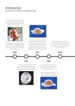
Evolution of DePuy Cemented Cups For almost 50 years, Ultra High Molecular Weight Polyethylene (UHMWPe) has been used as an acetabular bearing material bearing material that shows excellent clinical results.1-2 In 1977 the pressure injection flange was introduced to improve acetabular fixation and the In 1994 the UHMWPe used was upgraded to In 1962 Charnley implanted his stem for the first early pressurisation of the bone cement. The ENDURON™ polyethylene, a more consistent form time in combination with a UHMWPe acetabular incidence of radiolucent lines at the cement-bone of the material. “The...
Open the catalog to page 4
Cross-Linked Polyethylene (XLPE) n lull OIK h Wcar-RoiUnnt I Mm 1 lieh Wnphi I'l.^rttiik-rtc fm TtHat Hip RcpLxctnctm Engh et al reported a 95% reduction in the linear wear rate of MARATHON XLPE compared to ENDURON polyethylene at mean follow up of 5.7 years in 20067 In 2007 Home and Devane showed a 77% reduction in volumetric wear of MARATHON XLPE compared to ENDURON after 4 years The introduction of MARATHON Cross-Linked Polyethylene in 1998 was an evolutionary rather than a revolutionary advance in the adaptation of UHMWPe as an advanced bearing surface. The level of irradiation (50 kGy) is...
Open the catalog to page 5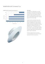
MARATHON XLPE Cemented Cup Size Range MARATHON XLPE Cemented Cup Size Range (mm) The introduction of MARATHON Cross-linked 36 polyethylene as a high performance PE bearing for cemented cup manufacture has allowed the existing size range to be extended to include a Bearing Diameter new 36 mm bearing diameter combined with a 45 mm outside diameter (please refer to the table opposite for the full size range). 26 An area of concern is the rate of wear at the bearing surface and the need to mimimise the amount of polyethylene wear debris produced (related to head size) that can lead to osteolysis...
Open the catalog to page 6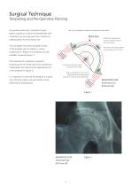
Surgical Technique Templating and Pre-Operative Planning Pre-operative planning is intended to assess The X-ray templates include the following information patient suitability to receive the MARATHON XLPE Cemented Cup and may save time in theatre by Dotted line represents the minimum required cement mantle thickness. helping predict the final implant size. X-ray templates have been provided for each Holes allow the reaming depth to be marked onto the X-ray. of the available sizes of implant in various magnifications. Digital X-ray templates are also available if required (Figure 1). The landmarks...
Open the catalog to page 7
Approach to the Acetabulum Use the approach with which you are most familiar to achieve the best surgical results. The MARATHON XLPE Cemented Cup Instrumentation is designed to accommodate all surgical approaches. Regardless of the surgical approach used, it is vital that a full 360 degree view of the acetabulum be achieved prior to beginning its preparation. The entire acetabular rim and transverse acetabular ligament should be identifiable. If the view is restricted it may be necessary to increase the incision length. Reaming Remove the labrum and any osteophytes from the acetabular rim. The...
Open the catalog to page 8
The size of reamer should then be increased incrementally and used to expand the cavity, taking care not to progress further medially. Spherical reaming should continue until good quality bone is exposed anteriorly and posteriorly, at which point further up-sizing of the reamer should stop. The reamer may be progressed superiorly so that good bone is exposed over the entire acetabulum. The final cavity will be slightly oval in shape (narrowest in the anterior/posterior direction), as defined by the quality of the underlying bone (Figure 4). It is important that the medial, anterior and posterior...
Open the catalog to page 9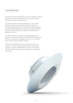
Cup Positioning Peer reviewed publications highlight the importance of acetabular component positioning in relation to short and long term outcomes during total hip arthroplasty for all types of bearing materials.12-16 Cup positioning should be varied to optimise fixation, range of motion, dislocation resistance and to minimise the likelihood of subluxation, impingement and edge loading. This may be assessed during pre-operative planning, acetabular preparation and cup trialling. Sub-optimal component positioning may lead to edge loading, dislocation, increased wear, and polyethylene fracture.12-16...
Open the catalog to page 10
Trial A trial cup exists for each definitive implant size. The trial should be attached to the introducer instrument (introducers are available for each of the head diameters) providing an opportunity to trial the final implant position in addition to checking the size. Trials are compatible with all sizes of introducer with mating features marked accordingly. The correct size of trial should sit within the acetabular cavity with 3-4 mm of clear space all around it. Figure 5 The introducer instrument provides a guide to allow correct orientation of the implant. When the shaft of the instrument...
Open the catalog to page 11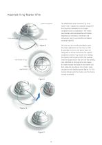
Assemble X-ray Marker Wire implant component The MARATHON XLPE Cemented Cup X-ray marker wire is supplied as a separate component that should be assembled to the implant component prior to implantation. The marker wire provides useful postoperative information regarding cup inclination, anteversion and X-ray marker wire retroversion, and its use should be considered locating hole The wire must be correctly orientated to give the proper appearance on the X-ray. In order to assemble the wire to the device, open the sterile pack as normal and remove the implant component and the X-ray marker wire....
Open the catalog to page 12
Prepare Implant Assemble the implant onto the appropriate size of introducer instrument. The implant has laser marking to identify when it is correctly assembled for the side of the operated hip (Figure 12). When correctly assembled, the exposed side marker “L” or “R” should be the same as the side of the operated hip (Figure 13). Before trimming the flange it may be useful to offer the implant up to the acetabulum to check the size. The flange should be trimmed to size (using the supplied scissors), away from the acetabulum. Figure 12 Markings on the flange relate back to the reamer diameters...
Open the catalog to page 13All Depuy Synthes catalogs and technical brochures
 Titanium Sternal Fixation System
34 Pages
 Small Battery Drive II
4 Pages
 Introducing The Variable Angle
12 Pages

Archived catalogs
 MatrixRIB®FixationSystem
86 Pages
 HEALIX ADVANCE
4 Pages
 HEALIX Anchor™ 3.4 mm
2 Pages
 3.5 mm LCP™ Medial
15 Pages
 RADIUS OF CURVATURE
3 Pages
 Building on Success
16 Pages
 2.0 mm LCP® Distal Ulna Plate
20 Pages
 2.4 mm VA LCP™
4 Pages
 Mandible Trauma Solutions
2 Pages
 Power line II
4 Pages
 Concorde
28 Pages
 LCP Intercarpal
31 Pages
 LCS® COMPLETE™
2 Pages
 Synthes TPLO.
8 Pages
 SynFix-LR System
56 Pages
 ATB Anterior Tension Band Plate
32 Pages
 CONDUIT™
15 Pages
 Brochure_FINAL
2 Pages
 DePuy Synthes
81 Pages
 Anspach
3 Pages
 Orthopedic Foot Instruments
32 Pages
 PINNACLE® Hip Solutions
12 Pages
 Corail
24 Pages
 S-ROM® NOILES™
68 Pages
 TRI-LOCK® Product Rationale
12 Pages
 Reclaim Surgical Technique
44 Pages
 Speed
Speed2 Pages
 attune
80 Pages
 HAMMERLOCK® 2
2 Pages
 DePuy Glenoid Solutions
2 Pages
 Trauma Solutions. Elbow
4 Pages
 Polar
Polar4 Pages
 Alveolar Distractor.
4 Pages
 Piezoelectric System
4 Pages
 Air Power Line II
6 Pages
 LCP Clavicle Hook Plate
4 Pages
 TruMatch Pin Guides
16 Pages
 P F N A
8 Pages
 SKILL, DEDICATION,
16 Pages
 Orthopaedics. Overview
20 Pages
 DURALOC
16 Pages
 REEF Surgical Technique
16 Pages
 MatrixNEURO
8 Pages
 Anspach XMax
4 Pages
 Anspach eMax 2 Plus
4 Pages
 Small Electric Drive
4 Pages
 Air Pen Drive
4 Pages
 Colibri II
4 Pages
 Spine
Spine25 Pages
 Expert Hindfoot Arthrodesis Nail
48 Pages
 LCP Distal Fibula Plates
32 Pages
 TomoFix
60 Pages
 Expert Tibial Nail PROtect
16 Pages
 Expert Tibia Nail
84 Pages
 Sacral Bars
16 Pages
 Pelvic C-Clamp
20 Pages
 Low Profile Pelvic System
16 Pages
 Proximal Femoral (Hook) Plate
24 Pages
 LCP
LCP24 Pages
 PFNA
PFNA112 Pages
 HCS 1.5, 2.4, 3.0
36 Pages
 LCP Wrist Fusion
32 Pages
 LCP Compact Hand
28 Pages
 VA-LCP Elbow
48 Pages
 Distal Radius
44 Pages
 Olecranon
30 Pages
 LCP Hook Plate
28 Pages
 DHP & Olecranon
4 Pages
 LCP S-A
4 Pages
 Epoca
Epoca4 Pages
 Philos
32 Pages
 MultiLoc
68 Pages


- DePuy Synthes bone plate
- Compression plate
- Metallic compression plate
- Locking compression plate
- Titanium compression plate
- Distal compression plate
- Orthopedic surgery instrument kit
- Interbody fusion cage
- Sterilization container
- Instrument sterilization container
- Arthrodesis nail
- Bone substitute
- Metallic intramedullary nail
- Femoral stem
- Anterior interbody fusion cage
- Arthrodesis plate
- Orthopedic surgery bone substitute
- Femoral intramedullary nail
- Metallic arthrodesis plate
- Knee prosthesis