- Catalogs
- Depuy Synthes
- REEF Surgical Technique
REEF Surgical Technique

REEF Surgical Technique
The REEF™ implant is specifically designed for addressing major femoral deficiencies, particularly Paprosky types 3A, 3B, and 4. It features a modular system for adaptability during surgery, distal diaphyseal anchorage, a complete hydroxyapatite coating for biological anchorage, and distal interlocking screws for initial mechanical stability.
The REEF prosthesis is a modular femoral implant that offers flexibility during intraoperative assembly. It ensures primary stability through a distal press-fit and interlocking screws, with a fully hydroxyapatite-coated stem for osteointegration and long-term fixation. Made from forged titanium alloy, it uses a hydroxyapatite coating similar to the CORAIL range.
Preoperative planning involves determining the level of the extended trochanteric osteotomy (ETO), locating the implantation level of the REEF stem, estimating component sizes, and setting the number and positions of interlocking screws using X-ray templates and radiographic images.
The surgical approach involves a transfemoral route with a large flap including the greater trochanter. The osteotomy is performed using a saw and drill guide plate, allowing the femur to be opened like a book. Thorough removal of the failed implant and surrounding materials is necessary, with potential bone-grafting.
Trial stems are selected based on distal diaphysis reaming, with stability assessed by distal stem position and primary stability in axial and rotational planes. The trial trochanteric component is mounted, and anteversion is adjusted. Trial reduction tests mobility and stability.
The final stem is mounted on a targeting frame for correct orientation. The stem is inserted to the planned level, and distal screw placement begins with the proximal screw for precision. Adequate distal fixation is crucial for primary stability until femoral osteotomy healing.
Post-operative care and weight-bearing regimens are essential for achieving long-term fixation and function. Patients must adhere strictly to post-operative instructions, including weight-bearing restrictions until osteointegration is confirmed. Regular follow-ups with radiographic assessments are recommended.
Examples of clinical cases and ordering information are provided to assist in the practical application and procurement of the REEF prosthesis. Several clinical cases demonstrate successful outcomes of revision surgeries and femoral reconstructions over various follow-up periods.
A comprehensive list of available implants, including ARTICUL/EZE trial heads, distal stems, femoral heads, trochanteric components, screws, and lateral wings, is provided. The document also lists the necessary instruments and trays for the procedures.
The document cites several studies and internal data supporting the use of hydroxyapatite-coated stems and other components in joint arthroplasty.
Contact details for DePuy Orthopaedics in various locations are provided for further inquiries.
Catalog excerpts

This publication is not intended for distribution in the USA. PRODUCT RATIONALE AND SURGICAL TECHNIQUE Distally-Interlocked Modular Femoral Reconstruction Prosthesis
Open the catalog to page 1
INTRODUCTION The REEF™ implant is based on the four following basic principles: • Distal diaphyseal anchorage • A modular system which makes it possible to adapt, at the intraoperative stage, to almost any situation encountered • Total hydroxyapatite coating to achieve biological anchorage, reconstruction and support1 CORAIL Revision • Distal interlocking screws to ensure initial mechanical stability before osteointegration takes place2,3 The REEF femoral implant is reserved for cases of major femoral deficiency (Paprosky types 3A, 3B and 4). This implant is not to be used in less severe revision...
Open the catalog to page 3
PRODUCT RATIONALE The REEF prosthesis is a modular femoral implant which allows flexibility during intraoperative assembly of the different components thanks to the range of available stem lengths and diameters. The REEF implant offers a customised solution for most joint reconstruction problems being faced. Primary stability is provided by virtue of a distal press-fit which is further facilitated by distal interlocking screws.2,3 The fully HA coated stem allows osteointegration throughout the stem affording long term secondary fixation.1,5,6 The REEF stem should not be used with cement. MetaphysealDiaphyseal...
Open the catalog to page 4
Trochanteric Component and dedicated locking screw (16 mm) Trochanteric Component and dedicated locking screw (26 mm) Anteversion Witness Marks Lateral Wings Materials The REEF range of implants are made from forged titanium alloy TiAl6V4 ELI ASTM F 136 and ISO5832-3. Hydroxyapatite Coating The REEF implant utilises the same HA coating as the well established CORAIL range which has over 25 years of clinical heritage and a minimum purity of 98% and has an average thickness of 150μm.7 Due to its bioactivity, this coating encourages bone on-growth and promotes fast and efficient osteointegration,...
Open the catalog to page 5
SURGICAL TECHNIQUE Preoperative planning makes it possible to: 1. Identify the lower level of the extended trochanteric osteotomy (ETO) required to fully remove the failed primary implant and any cement; this involves taking measurements in relation to several reference points (the top of the greater trochanter and the lesser trochanter, the femoral condyle, and any osteosynthesis material still in place). 2. Locate the level of implantation of the REEF stem, which can be measured from the reference point for the metaphyso-diaphyseal junction of the stem, as marked on the X-ray template, and...
Open the catalog to page 6
APPROACH Extended Trochanteric Osteotomy Regardless of the initial approach selected (posterior, lateral or anterior), it is obligatory that the approach be made via the transfemoral route (Wagner technique), with a large flap that includes the greater trochanter (Figure 1) instead of a simple trochanterotomy which is insufficient to expose any existing bone lesions and explant the failed hardware. There must be no interference with the vascularisation when handling the muscles and their insertions. The distal border of the osteotomy is made using a saw, around the lateral hemi-circumference...
Open the catalog to page 7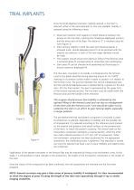
TRIAL IMPLANTS Once the distal diaphysis has been carefully reamed, a trial stem is selected, either of the same diameter or next size available. Stability is assessed using the following criteria: • Distal stem position with regards to height (distance between the groove on the trial stem, marking the metaphyso-diaphyseal junction, and the lower part of the flap). The distance ‘D’ is checked using the ruler (Figure 3). • Stem primary stability in both the axial and rotational planes is achieved (note: should adequate press-fit not be achieved with the original size selection, a stem of the next...
Open the catalog to page 8
FINAL IMPLANTS Assembly of the Targeting Frame The final stem corresponding to the trial implant in terms of length and diameter is mounted on the corresponding targeting frame (right/left). Using the “ANTE” and “POST” marking ensure the stem is correctly orientated before assembly with the targeting frame. When assembling the final Implant & the targeting frame, ensure the locking screw of the frame is aligned and fully seated in the corresponding hole on the distal stem. In addition, the orientation ‘’key’’ on the targeting frame should seat entirely into the corresponding recess in the stem,...
Open the catalog to page 9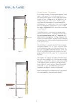
FINAL IMPLANTS Distal Screw Placement If not already attached, the appropriate targeting frame (right or left) replaces the handle. It is positioned on the cone and firmly locked in place. Again, ensure both surfaces are flush and the ‘locking key’ is seating in the corresponding recess in the implant. Should any gap occur here, the offset will incurs misalignment of the drill guides and the implant holes. Holes in the targeting device are designed to accept the drill guides and drill bits used to prepare the femoral cortices for the locking screws (Figure 7). For greater precision, screw placement...
Open the catalog to page 10
Placement of the trial trochanteric component and wing At this point, the trial trochanteric component and wing may be re-fitted in order to confirm that the length of the limb, stability of the prosthesis and anteversion have been restored (Figure 9). Before assembling any components care must be taken to ensure both surfaces are free from any debris or fluid that could interfere with the stability and strength of the taper connection. Surfaces must be cleaned and dried before assembly and impaction. The trial locking screws are differentiated from the implantable locking screws by a laser marked...
Open the catalog to page 11
FINAL IMPLANTS Warning: Use only the screw supplied with the definitive trochanteric component. Do not implant the trial screws (i.e. L93507 and L93510 supplied in the same sterile packaging. (Figure 10) Femoral Head Impaction After carefully cleaning and drying the stem taper, the appropriate femoral head is positioned and lightly impacted with the dedicated impactor (L93206) to engage the taper. A final reduction of the assembly is then performed. Femoral Reconstruction Reconstruction of the femoral shaft around the final implant is then undertaken. Re-attachment of the osteotomy is achieved...
Open the catalog to page 12All Depuy Synthes catalogs and technical brochures
 Titanium Sternal Fixation System
34 Pages
 Small Battery Drive II
4 Pages
 Introducing The Variable Angle
12 Pages

Archived catalogs
 MatrixRIB®FixationSystem
86 Pages
 HEALIX ADVANCE
4 Pages
 HEALIX Anchor™ 3.4 mm
2 Pages
 3.5 mm LCP™ Medial
15 Pages
 RADIUS OF CURVATURE
3 Pages
 Building on Success
16 Pages
 2.0 mm LCP® Distal Ulna Plate
20 Pages
 2.4 mm VA LCP™
4 Pages
 Mandible Trauma Solutions
2 Pages
 Power line II
4 Pages
 Concorde
28 Pages
 LCP Intercarpal
31 Pages
 LCS® COMPLETE™
2 Pages
 Synthes TPLO.
8 Pages
 SynFix-LR System
56 Pages
 ATB Anterior Tension Band Plate
32 Pages
 CONDUIT™
15 Pages
 Brochure_FINAL
2 Pages
 DePuy Synthes
81 Pages
 Anspach
3 Pages
 Orthopedic Foot Instruments
32 Pages
 PINNACLE® Hip Solutions
12 Pages
 Corail
24 Pages
 S-ROM® NOILES™
68 Pages
 TRI-LOCK® Product Rationale
12 Pages
 Reclaim Surgical Technique
44 Pages
 Speed
Speed2 Pages
 attune
80 Pages
 HAMMERLOCK® 2
2 Pages
 DePuy Glenoid Solutions
2 Pages
 Trauma Solutions. Elbow
4 Pages
 Polar
Polar4 Pages
 Alveolar Distractor.
4 Pages
 Piezoelectric System
4 Pages
 Air Power Line II
6 Pages
 LCP Clavicle Hook Plate
4 Pages
 TruMatch Pin Guides
16 Pages
 P F N A
8 Pages
 SKILL, DEDICATION,
16 Pages
 Orthopaedics. Overview
20 Pages
 DURALOC
16 Pages
 Marathon Cemented Cup
20 Pages
 MatrixNEURO
8 Pages
 Anspach XMax
4 Pages
 Anspach eMax 2 Plus
4 Pages
 Small Electric Drive
4 Pages
 Air Pen Drive
4 Pages
 Colibri II
4 Pages
 Spine
Spine25 Pages
 Expert Hindfoot Arthrodesis Nail
48 Pages
 LCP Distal Fibula Plates
32 Pages
 TomoFix
60 Pages
 Expert Tibial Nail PROtect
16 Pages
 Expert Tibia Nail
84 Pages
 Sacral Bars
16 Pages
 Pelvic C-Clamp
20 Pages
 Low Profile Pelvic System
16 Pages
 Proximal Femoral (Hook) Plate
24 Pages
 LCP
LCP24 Pages
 PFNA
PFNA112 Pages
 HCS 1.5, 2.4, 3.0
36 Pages
 LCP Wrist Fusion
32 Pages
 LCP Compact Hand
28 Pages
 VA-LCP Elbow
48 Pages
 Distal Radius
44 Pages
 Olecranon
30 Pages
 LCP Hook Plate
28 Pages
 DHP & Olecranon
4 Pages
 LCP S-A
4 Pages
 Epoca
Epoca4 Pages
 Philos
32 Pages
 MultiLoc
68 Pages


- DePuy Synthes bone plate
- Compression plate
- Metallic compression plate
- Locking compression plate
- Titanium compression plate
- Distal compression plate
- Orthopedic surgery instrument kit
- Interbody fusion cage
- Sterilization container
- Instrument sterilization container
- Arthrodesis nail
- Bone substitute
- Metallic intramedullary nail
- Femoral stem
- Anterior interbody fusion cage
- Arthrodesis plate
- Orthopedic surgery bone substitute
- Femoral intramedullary nail
- Metallic arthrodesis plate
- Knee prosthesis