- Catalogs
- Depuy Synthes
- TruMatch Pin Guides
TruMatch Pin Guides

TruMatch Pin Guides
This document serves as an addendum to the SIGMA High Performance Instruments Fixed Reference Surgical Technique, specifically addressing the integration of TRUMATCH Femoral and Tibial pin guides. Surgeons are advised to familiarize themselves with the necessary instruments and review the TRUMATCH Patient Proposal prior to the procedure.
Femoral Preparation:
1. Insert drill guides and place the femoral pin guide.
2. Drill anterior and distal pin holes, then remove the pin guide.
3. Position the distal femoral cutting block using the anterior reference guide.
4. Verify and perform distal femoral resection.
5. Use the fixed reference guide to position the 4-in-1 block and verify anterior resection.
6. Secure the 4-in-1 cutting block or HP femoral A/P chamfer block.
Tibial Preparation:
1. Insert drill guides and align the tibial guide.
2. Verify alignment and slope with the uprod extension.
3. Place anterior pins, remove guides, and perform proximal tibial resection.
Ensure patient-specific identifiers on the tibial pin guide are verified before use. Proper handling and placement stability are crucial, aligning the guide with the patient's anatomy as per the Patient Proposal.
Verify patient-specific identifiers on the femoral pin guide. Ensure proper seating and alignment, avoiding soft tissue impingement, and drill the necessary holes.
Attach the Universal Handle to the Distal Fixed Reference Guide, secure the block, and perform clean femoral resections.
Preoperative Considerations: Evaluate joint space loss with radiographs and review the Patient Proposal thoroughly.
Intraoperative Check-List: Display a wall chart summary in the OR for reference.
Verify bone cuts to ensure they are within 2 mm of planned values, maintaining varus/valgus alignment. Reassess guide placement and bone resections if deviations occur.
Use SIGMA HP Threaded Headless Sterile Pins for securing guides, especially in soft bone, and select long blades for large bones.
The primary reference surface is the anterior cortex of the femur. Ensure the guide clears the anterior femoral flange and sits flush on the cortical surface.
The primary reference surface is the anterior/medial aspect of the tibia. Apply most pressure anteriorly, with light downward force on the proximal arms.
TRUMATCH components are custom-made medical devices compliant with EU Council Directive 93/42/EEC. Contact information for DePuy International Ltd and DePuy Orthopaedics, Inc. is provided.
Catalog excerpts
JOINT RECONSTRUCTION with the SIGMA® High Performance PERSONALIZED SOLUTIONS This publication is not intended for distribution in the USA. SURGICAL TECHNIQUE S^GMA
Open the catalog to page 1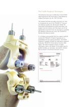
Pin Guide Surgical Technique The following steps are an addendum to the SIGMA High Performance (HP) Instruments, Fixed Reference Surgical Technique (Cat. No. 9075-02-000). This surgical technique provides instructions on how to incorporate the use of the TRUMATCH™ Femoral and Tibial pin guides into the broader SIGMA HP Instruments Fixed Reference Surgical Technique. The surgeon must be familiar with the proper use of the appropriate instruments that are necessary to complete the operation following the use of the TRUMATCH femoral and tibial pin guides. It is strongly recommended that the surgeon...
Open the catalog to page 2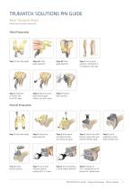
TRUMATCH SOLUTIONS PIN GUIDE Basic Surgical Steps SIGMA Total Knee System steps shown. Tibial Preparation Step 1: Insert drill guides Step 2A: Tibial guide placement Step 2B: Tibial guide alignment Step 3: Use of uprod extension. Verification of V/V alignment and slope Step 4: Placement of anterior pins. Use of HP uprod Step 5: Removal of drill guide and pin guide. Anterior pins left in place Step 6: Proximal tibial resection Step 1: Insert drill guides Step 2: Femoral pin guide placement Step 3: Drill anterior and distal pin holes and remove pin guide Step 4: Position the distal femoral cutting...
Open the catalog to page 3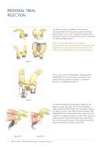
PROXIMAL TIBIAL RESECTION The tibial pin guide (in addition to the product packaging label) will have patient specific identifiers: patient name, lot no., size and patient anatomy (R/L). Verify the accuracy of these identifiers prior to opening the sterile package (Figure 1). Note: The size information was selected preoperatively based on the Patient Proposal. Final implant sizing may change due to intraoperative assessment of implant fit and/or joint gap balance. Prior to use, insert the TRUMATCH drill guides (P/N 200420925) into the two anterior openings of the plastic tibial pin guide by twisting...
Open the catalog to page 4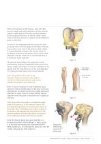
With the knee flexed at 90 degrees, place the tibial resection guide and uprod assembly onto the proximal anterior medial aspect of the tibia and both plateaux. Avoid using excessive force to seat the guide. Apply most of the force anterior to posterior while holding the guide as described. To assist in the medial/lateral positioning of the tibial pin guide, refer to the last page of the Patient Proposal that contains a top view of the patient’s tibial surface. It is recommended to observe the red line shown in the Patient Proposal to the patient’s bone and to check alignment with the raised...
Open the catalog to page 5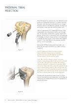
PROXIMAL TIBIAL RESECTION After drilling the two anterior pins, the TRUMATCH drill guides are removed by twisting in a counter-clockwise direction, while leaving the two anterior pins in place (Figure 7). Remove the tibial pin guide by moving it up and pulling it away from the anterior fixation pins. Slide the appropriate L/R 0 degree HP Proximal Tibial Cutting Block over the anterior fixation pins through the “0” mm holes marked with a square. (Figure 8) If desired, confirm the cut orientation with the angelwing. If necessary, the block may be shifted 2 mm proximally or distally by selecting...
Open the catalog to page 6
DISTAL FEMORAL RESECTION The femoral pin guide (in addition to the product packaging label) will have patient specific identifiers: patient name, lot no., size and patient anatomy (R/L). Verify the accuracy of these identifiers prior to opening the sterile package (Figure 9). Note: The size information was selected preoperatively based on the Patient Proposal. Final implant sizing may change due to intraoperative assessment of implant fit and/or joint gap balance. Prior to use, insert the TRUMATCH drill guides (P/N 200420925) into the two anterior and two distal openings of the plastic femoral...
Open the catalog to page 7
DISTAL FEMORAL RESECTION Evaluate the placement of the guide. The correct position is found when there is minimal or no toggling/ rocking of the femoral pin guide. It is not uncommon to see a 1 to 2 mm gap around the periphery of the guide due to cartilage loss. Insert two anterior pins and drill two distal holes using the appropriate drill guides (Figure 12). The anterior holes will be used to place the HP distal femoral cutting block to perform the distal femoral cut. The distal holes set the femoral rotation and match the fixed reference pin placement of the SIGMA HP femoral A/P chamfer block....
Open the catalog to page 8
Evaluate the distal cut using the reference guide or angelwing (Figure 14A). If needed, the block may be shifted 2 mm proximally or distally by selecting one of the appropriate offset holes adjacent to the “0” mm hole. For additional stability during the cut, an optional third, fixation pin can be placed through the cutting block in either the lower medial or lateral holes. Perform the distal femoral resection using a 1.19 mm thick saw blade (Figure 14B). Remove the HP Distal Femoral cutting guide and confirm the bone cuts are clean and without any under-cut bone fragments. Note: In order to...
Open the catalog to page 9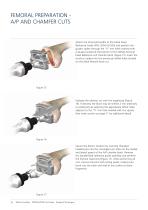
FEMORAL PREPARATION A/P AND CHAMFER CUTS Attach the Universal Handle to the Distal Fixed Reference Guide (P/N: 2004-20-920) and position the guide’s spikes through the “0” mm holes marked with a square located at the bottom of the SIGMA Femoral Fixed Reference A/P chamfer block (Figure 15). Insert the construct spikes into the previously drilled holes located on the distal femoral bone cut. Evaluate the anterior cut with the angelwing (Figure 16). If desired, the block may be shifted 2 mm anteriorly or posteriorly by selecting the appropriate offset holes adjacent to the “0” mm hole marked with...
Open the catalog to page 10
Note: If the Distal Fixed Reference Guide (P/N: 2004-20-920) is unavailable, two fixation pins can be inserted in the previously drilled distal femoral holes and used to set the location of the HP Femoral A/P chamfer block. The TRUMATCH Femoral Pin guide is designed to position the pin holes posteriorly on the femur which maintains the ability to move the block to resect 2 mm more bone anterior or 2 mm more bone posterior with the same size block regardless of whether the surgeon preference is anterior-down or posterior-up. However, if it is necessary to downsize the femoral component, the pin...
Open the catalog to page 11All Depuy Synthes catalogs and technical brochures
 Titanium Sternal Fixation System
34 Pages
 Small Battery Drive II
4 Pages
 Introducing The Variable Angle
12 Pages

Archived catalogs
 MatrixRIB®FixationSystem
86 Pages
 HEALIX ADVANCE
4 Pages
 HEALIX Anchor™ 3.4 mm
2 Pages
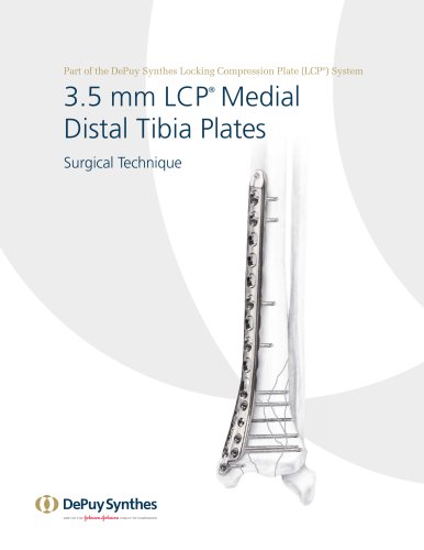 3.5 mm LCP™ Medial
15 Pages
 RADIUS OF CURVATURE
3 Pages
 Building on Success
16 Pages
 2.0 mm LCP® Distal Ulna Plate
20 Pages
 2.4 mm VA LCP™
4 Pages
 Mandible Trauma Solutions
2 Pages
 Power line II
4 Pages
 Concorde
28 Pages
 LCP Intercarpal
31 Pages
 LCS® COMPLETE™
2 Pages
 Synthes TPLO.
8 Pages
 SynFix-LR System
56 Pages
 ATB Anterior Tension Band Plate
32 Pages
 CONDUIT™
15 Pages
 Brochure_FINAL
2 Pages
 DePuy Synthes
81 Pages
 Anspach
3 Pages
 Orthopedic Foot Instruments
32 Pages
 PINNACLE® Hip Solutions
12 Pages
 Corail
24 Pages
 S-ROM® NOILES™
68 Pages
 TRI-LOCK® Product Rationale
12 Pages
 Reclaim Surgical Technique
44 Pages
 Speed
Speed2 Pages
 attune
80 Pages
 HAMMERLOCK® 2
2 Pages
 DePuy Glenoid Solutions
2 Pages
 Trauma Solutions. Elbow
4 Pages
 Polar
Polar4 Pages
 Alveolar Distractor.
4 Pages
 Piezoelectric System
4 Pages
 Air Power Line II
6 Pages
 LCP Clavicle Hook Plate
4 Pages
 P F N A
8 Pages
 SKILL, DEDICATION,
16 Pages
 Orthopaedics. Overview
20 Pages
 DURALOC
16 Pages
 Marathon Cemented Cup
20 Pages
 REEF Surgical Technique
16 Pages
 MatrixNEURO
8 Pages
 Anspach XMax
4 Pages
 Anspach eMax 2 Plus
4 Pages
 Small Electric Drive
4 Pages
 Air Pen Drive
4 Pages
 Colibri II
4 Pages
 Spine
Spine25 Pages
 Expert Hindfoot Arthrodesis Nail
48 Pages
 LCP Distal Fibula Plates
32 Pages
 TomoFix
60 Pages
 Expert Tibial Nail PROtect
16 Pages
 Expert Tibia Nail
84 Pages
 Sacral Bars
16 Pages
 Pelvic C-Clamp
20 Pages
 Low Profile Pelvic System
16 Pages
 Proximal Femoral (Hook) Plate
24 Pages
 LCP
LCP24 Pages
 PFNA
PFNA112 Pages
 HCS 1.5, 2.4, 3.0
36 Pages
 LCP Wrist Fusion
32 Pages
 LCP Compact Hand
28 Pages
 VA-LCP Elbow
48 Pages
 Distal Radius
44 Pages
 Olecranon
30 Pages
 LCP Hook Plate
28 Pages
 DHP & Olecranon
4 Pages
 LCP S-A
4 Pages
 Epoca
Epoca4 Pages
 Philos
32 Pages
 MultiLoc
68 Pages


- DePuy Synthes bone plate
- Compression plate
- Metallic compression plate
- Locking compression plate
- Titanium compression plate
- Distal compression plate
- Orthopedic surgery instrument kit
- Interbody fusion cage
- Sterilization container
- Instrument sterilization container
- Arthrodesis nail
- Bone substitute
- Metallic intramedullary nail
- Femoral stem
- Anterior interbody fusion cage
- Arthrodesis plate
- Orthopedic surgery bone substitute
- Femoral intramedullary nail
- Metallic arthrodesis plate
- Knee prosthesis