- Catalogs
- Depuy Synthes
- Variable Angle LCP Forefoot/Midfoot System 2.4/2.7
Variable Angle LCP Forefoot/Midfoot System 2.4/2.7

Variable Angle LCP Forefoot/Midfoot System 2.4/2.7
The Variable Angle LCP Forefoot/Midfoot System 2.4/2.7 is designed for osteotomies, arthrodeses, and fractures of the foot. It includes procedure-specific plates and screws for reconstructive foot surgery, available in stainless steel and titanium alloy.
The system offers up to 4 mm of tactile compression, variable angle screw holes allowing up to 15° off-axis angulation, and low-profile plates to minimize soft tissue irritation.
The system adheres to AO principles: anatomic reduction, stable fixation, preservation of blood supply, and early mobilization, guiding the use of variable angle locking technology for diverse fracture patterns.
The plates are indicated for fractures, deformations, revisions, and replantations of bones such as tarsals, metatarsals, and phalanges, especially in osteopenic bone.
This technique uses compression wires and forceps to achieve controlled compression. The wires are made of cobalt chromium alloy, and the forceps have a locking ratcheting mechanism to maintain compression during screw insertion.
Screws can be inserted using variable angle or pre-defined nominal angle techniques, allowing for a +/-15° deviation from the nominal trajectory.
Preparation involves selecting the appropriate plate and screws based on the specific procedure. Implantation includes preparing the joint surface, contouring the plate, positioning it, and applying reduction and compression using compression wires and forceps.
The system includes various fusion plates and screws, with specific instruments for each component. Detailed guidelines for reprocessing, care, and maintenance of Synthes instruments are available online.
- Drill Bits: Available in 1.8 mm and 2.0 mm diameters, with lengths of 110/85 mm, designed for quick coupling.
- Drill Sleeves: VA-LCP drill sleeves are available in conical and coaxial designs for both 2.4 mm and 2.7 mm systems.
- Depth Gauge: Measures screw lengths from 2.0 mm to 2.7 mm, with a range up to 40 mm.
- Pre-drilling: Two techniques are described: variable angle and pre-defined nominal angle. The variable angle allows for up to 15° deviation from the nominal trajectory, while the nominal angle uses coaxial drill guides.
- Implantation: Involves inserting VA locking screws using a screwdriver shaft and handle with quick coupling. The use of a torque limiter (1.2 Nm) is mandatory for final locking to ensure proper torque application.
- Optional Cortex Screws: Cortex screws can be inserted using universal drill guides, with pre-drilling done neutrally or off-center depending on the screw size.
- Includes various drill bits, drill sleeves, depth gauges, and screwdrivers designed for both 2.4 mm and 2.7 mm systems.
- Compression forceps and wires are available for additional fixation needs.
- Ensure proper joint reconstruction and screw placement using image intensification.
- Do not over-tighten screws to facilitate easy removal if necessary.
- Use sterile packed screws and plates when required, indicated by an 'S' suffix in the product number.
- Variable angle locking screws provide angular stability and can be used in both VA-LCP and standard LCP holes.
- Final locking requires the use of a torque limiting attachment to achieve maximum strength of the plate-screw interface.
- Compression Wires: Diameter 1.6 mm, Length 150 mm, with varying thread lengths of 40 mm, 35 mm, and 30 mm.
Instruments for Compression
- Bending Pliers for VA Locking Plates are available as an additional instrument.
Biomaterials Overview
- Synthes offers a range of synthetic and allogenic bone replacement materials, which provide uniform quality and unlimited availability without donor site complications.
- Products include Norian SRS, chronOS, and DBX, which are osteoconductive, resorbable, and can be enhanced with biological factors.
- These materials reduce surgery duration and are available in various forms with distinct biological properties.
Contact Information
- For more detailed product information or availability, contact your local Synthes representative.
Additional Information
- All technique guides are available as PDF files on the Synthes website.
Catalog excerpts

Variable Angle LCP Forefoot/Midfoot System 2.4/2.7. Procedure specific plates for osteotomies, arthrodeses and
Open the catalog to page 1
Introduction VA-LCP Forefoot/Midfoot Plates 2.4/2.7 2 Controlled Compression Technique 6 Screw Insertion Techniques 9 Surgical Technique Preparation 10 Product Information Screws 27 Synthes Biomaterials Overview 36 A Image intensifier control This description alone does not provide sufficient background for direct use of the product. Instruction by a surgeon experienced in handling this product is highly recommended Reprocessing, Care and Maintenance of Synthes Instruments For general guidelines, function control and dismantling of multi-part instruments, please contact your local sales representative...
Open the catalog to page 3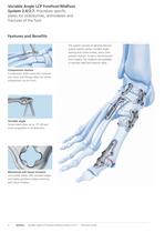
Variable Angle LCP Forefoot/Midfoot System 2.4/2.7. Procedure specific plates for osteotomies, arthrodeses and Compression feature Compression holes used with compres- sion wires and forceps allow for tactile Variable angle Screw holes allow up to 1 5° off-axis screw angulation in all directions. Minimized soft tissue irritation Low profile plates with rounded edges and highly polished surface minimize soft tissue irritation. The system consists of general and pro- cedure-specific plates, variable angle locking and cortex screws, and a com- pression feature, to aid in reconstructive foot surgery....
Open the catalog to page 4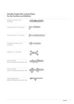
Variable Angle (VA) Locking Plates Straight Fusion Plate 2.4/2.7, L-Fusion Plate 2.4/2.7, VA locking T-Fusion Plate 2.4/2.7, VA locking Cloverleaf Fusion Plate 2.4/2.7, (refer to Technique Guide 036.001.234) (refer to Technique Guide 036.001.238) Opening Wedge Plates (refer to Technique Guide 036.001.236)
Open the catalog to page 5
AO Principles In 1958, the AO formulated four basic principles, which have become the guidelines for internal fixation.1, 2 The principles as applied to the Variable Angle LCP Forefoot / Midfoot System 2.4 / 2.7 are as follows: Anatomic reduction The use of variable angle locking technology allows fragment specific fixation by providing the flexibility to lock screws in trajectories that can diverge from the central axis of the plate hole. Variable screw angles provide fixation options for a variety of fracture patterns. Stable fixation Variable angle locking screws create a locked construct,...
Open the catalog to page 6
Indications The Straight Fusion Plates, T-Fusion Plates, L-Fusion Plates, Cloverleaf Fusion Plates and X-Plates of the Variable Angle LCP Forefoot / Midfoot System 2.4 / 2.7 are indicated for fractures, deformations, revisions and replantations of bones (e.g. tarsals, metatarsals and phalanges) and bone fragments, particularly in osteopenic bone. Synthes 5
Open the catalog to page 7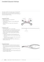
Controlled Compression Technique The plates included in the Variable Angle LCP Forefoot / Midfoot System 2.4 / 2.7 aid in reconstructive foot surgery by allowing controlled compression with the use of compression wires and compression forceps. Compression feature – Allows for up to 4 mm of compression – Tactile compression – Designed within the plate to minimize additional soft tissue dissection – Allows for final screw fixation after compression is achieved Compression wires – 1.6 mm diameter, 150 mm overall length – Seven thread lengths: 10, 15, 20, 25, 30, 35 and 40 mm – Stop feature allows...
Open the catalog to page 8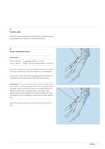
1 Position plate Place the plate on the bone, ensuring that the plate is placed appropriately according to the specific procedure. 2 Insert compression wires Instrument 03.211.410.01– Compression Wire л 1.6 mm, 03.211.440.01 length 150 mm, thread length 10 – 40 mm Estimate the appropriate thread length needed for the plate and bone combination. Bicortical fixation is recommended. Using a wire driver, insert the compression wire through the compression wire hole and through both bone cortices. Important: To minimize stripping of the bone threads, slow the insertion once the spherical stop of the...
Open the catalog to page 9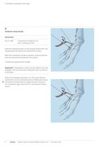
Controlled Compression Technique Compress using forceps with Compression Wire Move the ratcheting switch so the forceps ratchet when clos- ng preventing the spring from opening the forceps. Place the compression forceps in position, ensuring that the arms are around the compression wire spheres. Compress by squeezing the handles. Important: Compression is tactile, but be careful not to over compress. This may cause the compression wires to strip out When the ratcheting mechanism is in the correct position, compression can be maintained without holding the forceps. O This leaves the hands free...
Open the catalog to page 10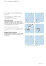
Screw Insertion Techniques The plate holes of the Variable Angle LCP Technology 2.4 / 2.7 accept 2.4 mm and 2.7 mm Variable Angle (VA) Locking Screws. Screws can be inserted using two different techniques: – Variable angle technique – Pre-defined nominal angle technique Variable angle technique To drill variable angle holes at a +/-15° deviation from the nominal trajectory of the locking hole, insert the tip of the conical VA-LCP drill sleeve (03.211.003 / 03.110.023) and key into the cloverleaf design of the VA-LCP hole. VA-LCP drill sleeve, conical, for Drill Bits (03.211.003/03.110.023) Note:...
Open the catalog to page 11
01.211 .X01 VA-/Cortex Screws 2.4, in Modular Tray, Vario Case System 01.211 .X02 VA-/Cortex Screws 2.7, in Modular Tray, Vario Case System 01.211 .X03 General Fusion Plates VA 2.4/2.7, in Modular Tray, Vario Case System 01.211.103 Instruments VA 2.4/2.7, in Modular Tray, Vario Case System Modular Tray, Vario Case System Select the plate according to the arthrodesis, osteotomy or fracture pattern and the anatomy of the patient. Note: This technique guide describes the application of VA locking plates for various indications in the forefoot and mid- foot of the "Variable Angle LCP Forefoot/Midfoot...
Open the catalog to page 12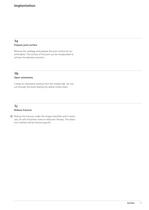
Prepare joint surface Remove the cartilage and prepare the joint surface for an arthrodesis. The surface of the joint can be manipulated to achieve the desired correction. Open osteotomy Create an osteotomy starting from the medial side. Do not cut through the bone leaving the lateral cortex intact. Reduce fracture O Reduce the fracture under the image intensifier and if neces- sary, fix with Kirschner wires or reduction forceps. The reduc- tion method will be fracture-specific.
Open the catalog to page 13All Depuy Synthes catalogs and technical brochures
 Titanium Sternal Fixation System
34 Pages
 Small Battery Drive II
4 Pages
 Introducing The Variable Angle
12 Pages

Archived catalogs
 MatrixRIB®FixationSystem
86 Pages
 HEALIX ADVANCE
4 Pages
 HEALIX Anchor™ 3.4 mm
2 Pages
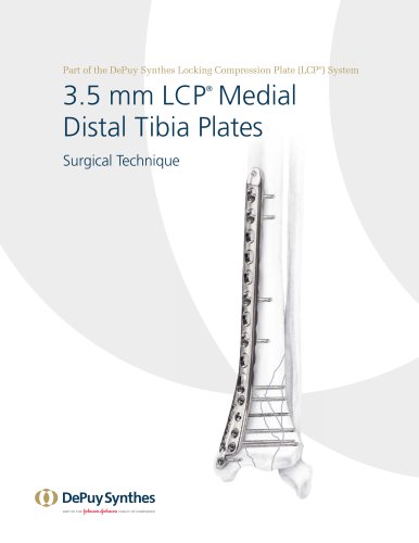 3.5 mm LCP™ Medial
15 Pages
 RADIUS OF CURVATURE
3 Pages
 Building on Success
16 Pages
 2.0 mm LCP® Distal Ulna Plate
20 Pages
 2.4 mm VA LCP™
4 Pages
 Mandible Trauma Solutions
2 Pages
 Power line II
4 Pages
 Concorde
28 Pages
 LCP Intercarpal
31 Pages
 LCS® COMPLETE™
2 Pages
 Synthes TPLO.
8 Pages
 SynFix-LR System
56 Pages
 ATB Anterior Tension Band Plate
32 Pages
 CONDUIT™
15 Pages
 Brochure_FINAL
2 Pages
 DePuy Synthes
81 Pages
 Anspach
3 Pages
 Orthopedic Foot Instruments
32 Pages
 PINNACLE® Hip Solutions
12 Pages
 Corail
24 Pages
 S-ROM® NOILES™
68 Pages
 TRI-LOCK® Product Rationale
12 Pages
 Reclaim Surgical Technique
44 Pages
 Speed
Speed2 Pages
 attune
80 Pages
 HAMMERLOCK® 2
2 Pages
 DePuy Glenoid Solutions
2 Pages
 Trauma Solutions. Elbow
4 Pages
 Polar
Polar4 Pages
 Alveolar Distractor.
4 Pages
 Piezoelectric System
4 Pages
 Air Power Line II
6 Pages
 LCP Clavicle Hook Plate
4 Pages
 TruMatch Pin Guides
16 Pages
 P F N A
8 Pages
 SKILL, DEDICATION,
16 Pages
 Orthopaedics. Overview
20 Pages
 DURALOC
16 Pages
 Marathon Cemented Cup
20 Pages
 REEF Surgical Technique
16 Pages
 MatrixNEURO
8 Pages
 Anspach XMax
4 Pages
 Anspach eMax 2 Plus
4 Pages
 Small Electric Drive
4 Pages
 Air Pen Drive
4 Pages
 Colibri II
4 Pages
 Spine
Spine25 Pages
 Expert Hindfoot Arthrodesis Nail
48 Pages
 LCP Distal Fibula Plates
32 Pages
 TomoFix
60 Pages
 Expert Tibial Nail PROtect
16 Pages
 Expert Tibia Nail
84 Pages
 Sacral Bars
16 Pages
 Pelvic C-Clamp
20 Pages
 Low Profile Pelvic System
16 Pages
 Proximal Femoral (Hook) Plate
24 Pages
 LCP
LCP24 Pages
 PFNA
PFNA112 Pages
 HCS 1.5, 2.4, 3.0
36 Pages
 LCP Wrist Fusion
32 Pages
 LCP Compact Hand
28 Pages
 VA-LCP Elbow
48 Pages
 Distal Radius
44 Pages
 Olecranon
30 Pages
 LCP Hook Plate
28 Pages
 DHP & Olecranon
4 Pages
 LCP S-A
4 Pages
 Epoca
Epoca4 Pages
 Philos
32 Pages
 MultiLoc
68 Pages


- DePuy Synthes bone plate
- Compression plate
- Metallic compression plate
- Locking compression plate
- Titanium compression plate
- Distal compression plate
- Orthopedic surgery instrument kit
- Interbody fusion cage
- Sterilization container
- Instrument sterilization container
- Arthrodesis nail
- Bone substitute
- Metallic intramedullary nail
- Femoral stem
- Anterior interbody fusion cage
- Arthrodesis plate
- Orthopedic surgery bone substitute
- Femoral intramedullary nail
- Metallic arthrodesis plate
- Knee prosthesis