- Catalogs
- EHD imaging
- MaxCam‐2020e‐TE
MaxCam‐2020e‐TE
1 /39Pages
MaxCam‐2020e‐TE
1 /39Pages
Catalog excerpts
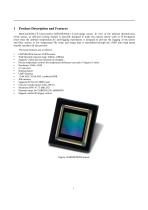
MaxCam2020e-TE is powered by GSENSE2020e 1.2-inch image sensor. In view of the inherent thermal noise of the sensor, an efficient cooling module is specially designed to make the camera sensor work at 35-40 degrees lower than the ambient temperature. An anti-fogging mechanism is designed to prevent the fogging of the sensor and filter surface at low temperature.The video and image data is transmitted through the USB3 ultra high speed transfer interface for fast preview. The basic features are as follows : • GSENSE2020e Science CMOS sensor • Wide Spectral response range: 400nm -1000nm • Supports...
Open the catalog to page 4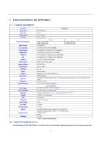
2 Camera parameters and performance 2.1 Camera parameters Table 1 camera parameters 2.2 Spectral response curve
Open the catalog to page 5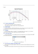
Figure 2 Spectral response curve Camera operation mode support: video mode or trigger mode. Camera trigger mode support: soft trigger mode or external trigger mode. The camera has a built-in 512MB (4Gb) DDR3 buffer, which can effectively improve the stability of USB3 data transmission and ensure that the camera does not lose frames when working. The camera supports additive or averaged 1x1 to 8x8 digital binning, and averaged 1x1 to 2x2 hardware binning. Hardware binning can achieve higher frame rates than software binning. The camera supports HCG^ LCG and HDR mode, HCG has low Readout Noise,...
Open the catalog to page 6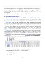
will automatically switch to the USB 5V power supply and the camera can work normally in passive cooling mode. The camera's cooling system is cooled by TEC. It uses an external heat dissipation structure and a fan to assist heat dissipation. The working temperature can be adjusted to a specific value, and the effective cooling temperature can be lower than the ambient temperature by 30 - 35 °C. The efficient cooling system guarantees extremely low dark current levels. The TEC system is controlled by PID algorithm, so that the TEC can be accurately adjusted to the target temperature, and the temperature...
Open the catalog to page 7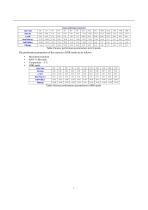
Table 4 Sensor performance parameters in HDR mode
Open the catalog to page 8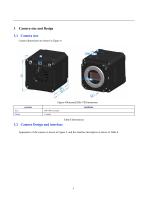
Camera size and Design 3.1 Camera size Camera dimensions are shown in Figure 4. Figure 4 Maxcam2020e-TE Dimensions parameter 3.2 Camera Design and interface Appearance of the camera is shown in Figure 5, and the interface description is shown in Table 6.
Open the catalog to page 9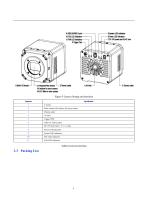
Figure 5 Camera Design and interface Sequence Filter window,AR window for mono camera Thermo outlet Table 6 Camera Interface
Open the catalog to page 10
Figure 6 packing information Standard Packing A Packing case specifications L:50cm W:30cm H:30cm (20pcs, 12~17Kg/ carton),Not shown in the figure Power adapter : input: AC 100~240V 50Hz/60Hz,output: DC 19V 4A High‐speed USB3.0 A male to B male gold‐plated head data cable/1.5m CD (Driver and application software, Ø12cm) OPTIONAL Optional accessories
Open the catalog to page 11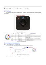
Rear appearance of the camera is shown in Figure 7, and the pin signals definition of the external IO connector are in Table 8. Table 8 pin signal definition In the I/O control of the camera, the Opto-isolated input circuit is shown in Figure 8. Logic 0 input level: 0~2.2VDC (OPTO_IN pin)
Open the catalog to page 12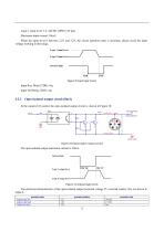
Logic 1 input level: 3.3~24VDC (OPTO_IN pin) Maximum input current: 30mA When the input level is between 2.2V and 3.2V, the circuit operation state is uncertain, please avoid the input voltage working in this range. Logic 1 input level Logic 0 input level Internal logic Figure 9 Input logic levels Input Rise Delay (TDR): 6us Input Fall Delay (TDF): 6us The opto-isolated output maximum current is 30mA. Internal logic Logic 0 output level The electrical characteristics of the opto-isolated output (external voltage 5V, external resistor 1K) are shown in Table 9.
Open the catalog to page 13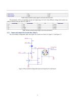
output fall time Output rise delay Output fall delay Table 9 Opto-isolated output signal's electrical characteristics The parameters of the corresponding current and output logic low level when different voltages and resistors are used in external circuit are shown in Table 10. external voltage 3.3V 5V 12V 24V External resistor Table 10 Opto-isolated output logic's low level parameters Input and output I/O circuit (line 2/line3 ) The non-isolated configurable input and output I/O circuits are shown in Figure 12 and Figure 13. Figure 12 Non-isolated configurable input and output I/O circuit (line2)...
Open the catalog to page 14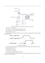
Figure 13 Non-isolated configurable input and output I/O circuit (line3) 1. Line2/line3 is set as input pin Logic 0 input level: 0~0.6VDC (DIR_GPIO1/DIR_GPIO2 pins) Logic 1 input level: 2.0~24VDC (DIR_GPIO1/DIR_GPIO2 pins) Maximum input current: 25mA When the input level is between 0.6V and 2.0V, the circuit action state is uncertain, please avoid the input voltage working in this range. Figure 14 Input logic levels To prevent damage to the GPIO pins, please connect the pin GND first, and then input voltage to the Line2 pin. Input Rise Delay (TDR): 0.02us Input Fall Delay (TDF): 0.02us 2. Line2/line3...
Open the catalog to page 15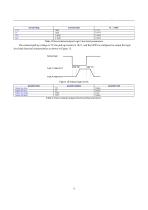
Table 12 Non-isolated output electrical characteristics
Open the catalog to page 16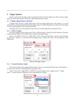
Trigger function After the camera enters the trigger mode, it automatically enters the wait-for-trigger state. After receiving a trigger signal, the camera starts exposure, and starts to output image data after exposure. 5.1 Trigger signal source selection In trigger mode, the type of trigger signal source can be the trigger signal given by the software, or it can be connected by an external level signal. The external trigger signal can be input through the pin isolated by the optocoupler, or it can be input through the non-isolated tube pin input. Soft trigger delay is ms level, generally not...
Open the catalog to page 17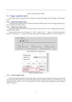
Figure 17 External trigger settings In the trigger mode, the acquisition mode is divided into: single-frame trigger, multi-frame trigger, counter trigger mode. The single-frame trigger mode refers to the operation mode in which the camera receives one trigger signal, exposes once, and outputs one frame of image. Multi-frame trigger mode refers to the operation mode in which the camera receives a trigger signal and outputs multiple frames of images. Trigger number can be set in the range of 1~ 65535. "Burst Count = 1” means a one-frame image output, Figure 18, "Burst Count = 3” means a three-frame...
Open the catalog to page 18All EHD imaging catalogs and technical brochures
 SCM-E10 Series Microcopy Cameras
4 Pages
 MaxCam‐4040UV‐TE
44 Pages
- Microscopy
- Compound microscope
- Laboratory microscope
- Desktop microscope
- LED microscope
- Laboratory software
- CMOS camera
- Camera with USB port
- Acquisition software
- Medical camera
- Measurement software
- Full HD camera
- Microscope camera
- HD camera
- Recording software
- Fluorescence microscope
- Digital microscope
- Real-time software
- Ultra-high resolution camera
- Compact microscope