- Catalogs
- EHD imaging
- MaxCam‐4040UV‐TE
MaxCam‐4040UV‐TE
1 /44Pages
MaxCam‐4040UV‐TE
1 /44Pages
Catalog excerpts
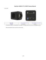
MaxCam-4040UV-TE sCMOS Camera Manual Camera Model All materials related to this publication are subject to change without notice and are copyrighted by EHD. Please download the latest version from www.ehd.de
Open the catalog to page 2
The MaxCam-4040UV-TE sCMOS Camera Help Manual
Open the catalog to page 3
The MaxCam-4040UV-TE sCMOS Camera Help Manual
Open the catalog to page 4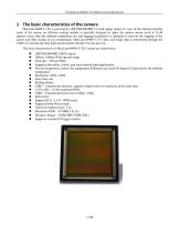
The MaxCam-4040UV-TE sCMOS Camera Help Manual MaxCam-4040UV-TE is powered by GSENSE4040BSI 3.2-inch image sensor. In view of the inherent thermal noise of the sensor, an efficient cooling module is specially designed to make the camera sensor work at 35-40 degrees lower than the ambient temperature.An anti-fogging mechanism is designed to prevent the fogging of the sensor and filter surface at low temperature. MaxCam-4040UV-TE video and image data is transmitted through the USB3 or CameraLink ultra high speed transfer interface for fast preview. The basic characteristics of MaxCam-4040UV-TE Camera...
Open the catalog to page 5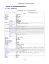
The MaxCam-4040UV-TE sCMOS Camera Help Manual Table 1 MaxCam-4040UV-TE camera specification
Open the catalog to page 6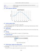
The MaxCam-4040UV-TE sCMOS Camera Help Manual Camera operation mode support: Video Mode or Trigger Mode. Camera Trigger Mode supports: Soft Trigger Mode(Software) or External Trigger Mode(Isolated input, GPIO0, GPIO1, Counter or PWM). Camera has a built-in 1024MB (8Gb) DDR3 buffer, which can effectively the camera does not lose frames when working. MaxCam-4040UV-TE supports additive or averaged 1x1 to 8x8 digital binning. Camera supports HCG and LCG mode. HCG has low Readout Noise, LCG has higher Full Well. Users can choose different modes according to different applications. When the DC19V power...
Open the catalog to page 7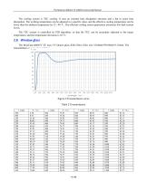
The MaxCam-4040UV-TE sCMOS Camera Help Manual The cooling system is TEC cooling. It uses an external heat dissipation structure and a fan to assist heat dissipation. The working temperature can be adjusted to a specific value, and the effective cooling temperature can be lower than the ambient temperature by 35 - 40 °C. The efficient cooling system guarantees extremely low dark current levels. The TEC system is controlled by PID algorithm, so that the TEC can be accurately adjusted to the target temperature, and the temperature deviation is 0.1°C. 2.8 Window glass The MaxCam-4040UV-TE uses UV...
Open the catalog to page 8
The MaxCam-4040UV-TE sCMOS Camera Help Manual
Open the catalog to page 9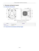
The MaxCam-4040UV-TE sCMOS Camera Help Manual
Open the catalog to page 10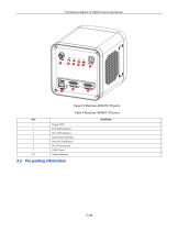
The MaxCam-4040UV-TE sCMOS Camera Help Manual Figure 5 MaxCam-4040UV-TE ports Table 4 MaxCam-4040UV-TE ports CameraLink port
Open the catalog to page 11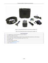
The MaxCam-4040UV-TE sCMOS Camera Help Manual Figure 6 The packing information of the MaxCam-4040UV-TE Table 5 The packing information of the MaxCam-4040UV-TE Standard Packing information Power cord. National standard, American standard, European standard, British standard power cord for choosing Power adapter: input: AC 100~240V 50Hz/60Hz, output: DC19 V 4.74A One external trigger control cable 2 CameraLink cables(Optional Accessory) capture card(Optional Accessory)
Open the catalog to page 12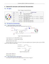
The MaxCam-4040UV-TE sCMOS Camera Help Manual Table 6 Trigger pin signal definitions In the I/O control of the camera, the opto-isolated input circuit is shown in Logic 0 input level: 0~2.2VDC (OPTO_IN pin) Logic 1 input level: 3.3~24VDC (OPTO_IN pin) Maximum input current: 30mA When the input level is between 2.2V and 3.2V, the circuit operation state is uncertain, please do not let SWIR camera work within this voltage range. Logic 1 input level Logic 0 input level Internal logic Figure 8 Input logic levels Input rise delay (TDR): 6us Input fall delay (TDF): 6us In the camera I/O control, the...
Open the catalog to page 13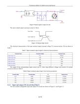
The MaxCam-4040UV-TE sCMOS Camera Help Manual The opto-isolated output maximum current is 30mA. The electrical characteristics of the opto-isolated output (external voltage 5V, external resistor 1K) are shown in Table 7. Table 7 Opto-isolated output signal's electrical characteristics The non-isolated configurable input and output I/O circuits are shown in Figure 11 and Figure 12.
Open the catalog to page 14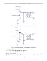
The MaxCam-4040UV-TE sCMOS Camera Help Manual Figure 11 Non-isolated configurable input and output I/O circuit (line2) Figure 12 Non-isolated configurable input and output I/O circuit (line3) 1. Line2/line3 is set as input pin Logic 0 input level: 0~0.6VDC (DIR_GPIO1/DIR_GPIO2 pins) Logic 1 input level: 2.0~24VDC (DIR_GPIO1/DIR_GPIO2 pins) Maximum input current: 25mA When the input level is between 0.6V and 2.0V, the circuit action state is uncertain, please avoid the input voltage 11 / 43
Open the catalog to page 15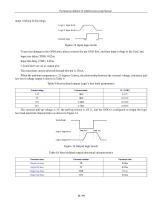
The MaxCam-4040UV-TE sCMOS Camera Help Manual range working in this range. To prevent damage to the GPIO pins, please connect the pin GND first, and then input voltage to the Line2 pin. Input rise delay (TDR): 0.02us Input fall delay (TDF): 0.02us The maximum current allowed through this pin is 25mA. When the ambient temperature is 25 degrees Celsius, the relationship between the external voltage, resistance and low-level valtage output is shown in Table 9. Table 9 Non-isolated output Logic's low level parameters
Open the catalog to page 16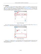
The MaxCam-4040UV-TE sCMOS Camera Help Manual There is a Cooling group on the left sidebar in EHDView. To enable the Cooling function, an external 19V power supply is required. By default, the TEC is turned on. One can set the Target Temperature. After entering the value, click "Apply", and the sensor temperature will gradually approach to the Target Temperature. At the same time, EHDView can display the current temperature in real time. And the cooling effect can reach about 35-40 degrees lower than the ambient temperature, as shown in Figure 15. Figure 15 TEC settings The Fan has two gears...
Open the catalog to page 17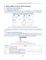
The MaxCam-4040UV-TE sCMOS Camera Help Manual The trigger function can be found on the Capture & Resolution group on the Camera Sidebar in EHDView. When the camera is opened, it is in Video Mode as shown in Figure 17 on the left. In Video Mode, Auto Exposure, Exposure Target, Exposure Time and Gain can be set. One can switch to Trigger Mode by checking the Trigger Mode check box. After the Trigger Mode is checked, the Capture & Resolution group will switch to Trigger Mode as shown in Figure 17 on the right. Where, the Trigger Source, Exposure Time, Gain, Single, Loop, Multiple, Frame Box, and...
Open the catalog to page 18All EHD imaging catalogs and technical brochures
 SCM-E10 Series Microcopy Cameras
4 Pages
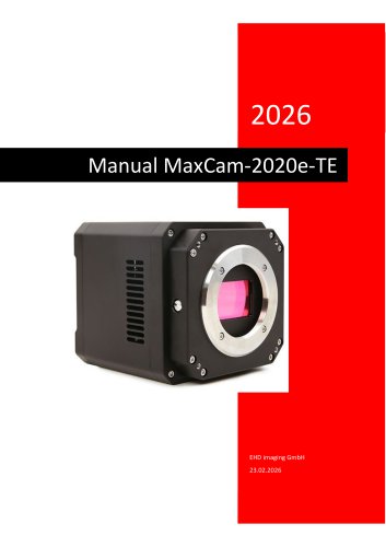 MaxCam‐2020e‐TE
39 Pages
- Microscopy
- Compound microscope
- Laboratory microscope
- Desktop microscope
- LED microscope
- Laboratory software
- CMOS camera
- Camera with USB port
- Acquisition software
- Medical camera
- Measurement software
- Full HD camera
- Microscope camera
- HD camera
- Recording software
- Fluorescence microscope
- Digital microscope
- Real-time software
- Ultra-high resolution camera
- Compact microscope