- Catalogs
- EMUGE-Werk Richard Glimpel
- EMUGE Clamping Technology

- Company
- Products
- Catalogs
- News & Trends
- Exhibitions
EMUGE Clamping Technology

EMUGE Clamping Technology
EMUGE-Werk Richard Glimpel GmbH & Co. KG, part of the EMUGE-FRANKEN group, specializes in precision tools for thread and bore production, as well as tool and workpiece clamping. The company has a rich history of over 100 years in precision and innovation, offering a comprehensive tool system solution from machine spindle to workpiece clamping.
EMUGE-FRANKEN is a global entity with a presence in all major industrial nations, supported by over 400 customer consultants. The company provides application-specific advice and develops special tools tailored to customer needs.
The catalogue highlights a diverse range of products including taps, cold-forming taps, thread milling cutters, twist drills, dies, thread rolls, tool holders, and thread gauges. These products are designed to enhance productivity and are complemented by standard and special solutions for workpiece clamping.
EMUGE-FRANKEN has been manufacturing clamping devices since 1950, establishing itself as a full-range supplier. The clamping technology division has evolved significantly, driven by innovation and a commitment to quality. The company develops all clamping devices in Germany, ensuring high precision and durability.
EMUGE-FRANKEN offers comprehensive service and support, including expert advice, start-up support, and maintenance services. The company aims to provide innovative clamping concepts that integrate seamlessly into customer processes.
The catalogue serves as a resource for discovering new possibilities in clamping technology, showcasing EMUGE-FRANKEN's expertise and commitment to quality and innovation.
- Functional Description: Utilizes two drawbars to actuate wedge jaws and a clamping bush for clamping rotor shafts of electric motors. Features a floating end stop to prevent axial jamming.
- Advantages: Independent clamping points for diameter and square clamping, optimal radial clearance.
- Technical Data: Clamping point diameter: 61 mm, square: 55 mm, concentricity: 5 µm, torque: 135 Nm, weight: 39 kg.
- Functional Description: Hydraulic clamping via an integrated piston, requiring a center point for support. Features a pendulum stop for axial run-out error compensation.
- Advantages: High-precision and low-deformation clamping, especially for thin-walled components.
- Technical Data: Clamping diameter: 24 mm, concentricity: 5 µm, torque: 12 Nm, weight: 10 kg.
- Functional Description: Uses drawbars to actuate a collet and face clamping fingers for secure clamping in small spaces.
- Advantages: Pre-centring via collet, efficient use of space.
- Technical Data: Clamping diameter: 115.1 mm, concentricity: 12 µm, weight: 28 kg.
- Functional Description: Utilizes pressure springs and a tie rod for centring and face clamping, with pneumatic release.
- Advantages: Low-deformation clamping, adaptable for various workpieces.
- Technical Data: Clamping diameter: 46.9 - 70 mm, concentricity: 5 µm, torque: 35 Nm, weight: 60 kg.
- Functional Description: Aligns housing parts using system springs and twin taper collet, suitable for electron beam welding.
- Advantages: Plastic clamping elements for protection, cost-effective.
- Technical Data: Clamping diameter: 45.6 / 77 mm, concentricity: 20 µm, weight: 50 kg.
- Functional Description: Pneumatic clamping for internal and face machining, with sealing air for protection.
- Advantages: High-precision clamping, dual-function sealing air.
- Technical Data: Clamping diameter: 6 mm, concentricity: 5 µm, torque: 7 Nm, weight: 12 kg.
- Functional Description: Initiated via a machine-side drawbar, with quick-change connection for efficient operation.
Functional Description: Utilizes a drawbar and quick-change connection to transmit clamping force to a collet with protruding segments fitting the gear profile.
Advantages: Precise fit, saves additional clamping, quick-change connection.
Technical Data: Clamping diameter: 138.5 mm, Concentricity: 12 µm, Total length: 389 mm, Weight: 26 kg.
Functional Description: Uses EMUGE power transmission for centering and clamping in two planes.
Advantages: Accurate alignment, protection against soiling, adaptable for different sizes.
Technical Data: Clamping diameter: 171 mm, Concentricity: 5 µm, Total length: 710 mm, Weight: 97 kg.
Functional Description: Clamping via drawbar and quick-change connection with integrated force reduction.
Advantages: Uniform force distribution, optimal support.
Technical Data: Clamping diameter: 42-56 mm, Concentricity: 5 µm, Total length: 430 mm, Weight: 30 kg.
Functional Description: Mounted with ball bearing, clamping initiated by manual torque.
Advantages: Exchangeable elements, high centring accuracy, smooth operation.
Technical Data: Clamping diameter: 66-84 mm, Concentricity: 4 µm, Total length: 441 mm, Weight: 90 kg.
Functional Description: Uses disc spring assembly and manual torque for clamping.
Advantages: Stable support, two clamping points.
Technical Data: Clamping diameter: 337.5 mm, Concentricity: 12 µm, Total length: 579 mm, Weight: 400 kg.
Functional Description: Dual drawbars actuate wedge-shaped jaws for clamping.
Advantages: Accurate alignment, protection against soiling, enables machining of both ends.
Technical Data: Clamping diameter: 45 mm, Concentricity: 18 µm, Total length: 700 mm, Weight: 46.5 kg.
Functional Description: Clamping via disc spring assembly and cross wedge.
Advantages: Precise fit for complex designs.
Technical Data: Clamping diameter: 58 mm, Concentricity: 5 µm, Total length: 202 mm, Weight: 5 kg.
Functional Description: Uses disc spring and clamping bush for high precision.
Advantages: High accuracy, integrated pin for status check, compensates for errors.
Technical Data: Not fully provided in the document.
- Functional Description: Utilizes a drawbar with quick-change connection to actuate clamping bushes directly under the cams of the workpiece.
- Advantages: Precise clamping despite small diameter and great length, two clamping points for alignment, and deformation-free clamping of sensitive workpieces.
- Technical Data: Clamping diameter of 22 mm, concentricity of 15 µm, and transferable torque of 10 Nm.
- Functional Description: Initiated via two drawbars, actuating a double taper collet and a movable end stop to compensate for axial run-out errors.
- Advantages: Compensation of axial errors, movable end stop, and reduced setup times.
- Technical Data: Clamping diameter of 34 mm, concentricity of 10 µm.
- Functional Description: Clamping initiated via a drawbar and clamping bolt, with a pendulum stop to prevent deformation.
- Advantages: Accurate alignment with two independent clamping levels, pendulum stop for surface accuracy, and optimized chip removal.
- Technical Data: Clamping diameter of 36 mm, concentricity of 5 µm, and transferable torque of 100 Nm.
- Functional Description: Uses a drawbar to transmit clamping to the rear clamping sleeve, with a centering point for support.
- Advantages: Low-deformation clamping, reliable torque transmission, and retractable end stop for machining.
- Technical Data: Clamping diameter of 22/43 mm, concentricity of 7 µm, and transferable torque of 60 Nm.
- Functional Description: Clamping initiated via a thrust bar, with a fixed collet for narrow clamping range.
- Advantages: Low-deformation clamping, optimal surface protection, and slim design.
- Technical Data: Clamping diameter of 9.1 mm, concentricity of 15 µm, and transferable torque of 4 Nm.
- Functional Description: Manually generated torque transmitted via a tilt ring to a rectangular collet.
- Advantages: Resistant to soiling, optimal clamping despite narrow area.
- Technical Data: Clamping diameter of 25 x 27 mm, concentricity of 15 µm.
- Functional Description: Clamping initiated via a drawbar, with two decoupled clamping bushes for bore accuracy.
- Advantages: Compensation of bore inaccuracies, machining of different workpiece lengths.
Functional Description: Utilizes a diaphragm system (SM) for pre-centering and hydraulic clamping via an integrated piston. A 'zero tooth' aids in workpiece alignment.
Advantages: Resistant to soiling, excellent repeat accuracy, easy jaw change, and equipped with air system control.
Technical Data: Clamping diameter of 126 mm, concentricity of 5 µm, total length of 172 mm, and weight of 39 kg.
Functional Description: Clamping initiated via a drawbar and quick-change connection, fitting precisely in the gear profile.
Advantages: Precise fit, saving additional clamping, and quick-change connection.
Technical Data: Clamping diameter of 106.5 mm, concentricity of 12 Nm, total length of 382 mm, and weight of 27 kg.
Functional Description: Hydraulic clamping via an integrated piston, with a pre-centering cover for loading aid.
Advantages: Slim design, high-precision clamping, and high transmissible torque.
Technical Data: Clamping diameter of 30 mm, concentricity of 5 µm, transferable torque of 100 Nm, total length of 300 mm, and weight of 35 kg.
Functional Description: Manual torque initiates clamping in two planes, with an intermediate sleeve for offset clamping diameter.
Advantages: Optimal clamping in two planes, connection via intermediate sleeve.
Technical Data: Clamping diameter of 266 mm, concentricity of 10 µm, transferable torque of 600 Nm, total length of 308 mm, and weight of 140 kg.
Functional Description: Clamping via drawbar and quick-change connection, with integrated spring assembly for force reduction.
Advantages: Low-deformation clamping, force reduction, and quick-change connection.
Technical Data: Clamping diameter of 42.1 mm, concentricity of 5 µm, transferable torque of 37 Nm, total length of 410 mm, and weight of 35 kg.
Functional Description: Pre-centering via diaphragm system, with hydraulic face clamping.
Advantages: Resistant to soiling, quick-change system, and excellent holding force.
Technical Data: Clamping diameter of 110 mm, repeat accuracy of 10 µm, transferable torque of 20 µm, total length of 303 mm, and weight of 55 kg.
Functional Description: Clamping via two drawbars, with independent clamping levels for alignment.
Advantages: Accurate alignment, alignable clamping device, and large jaw strokes.
Technical Data: Clamping diameter of 27/50 mm, concentricity of 20 µm, total length of 286 mm, and weight of 25 kg.
Functional Description: The clamping chuck is positioned at a 90° offset on the base flange, aligning the bore with the machine spindle axis. Clamping is initiated by the diaphragm's inherent tension and released hydraulically.
Advantages: Unbalance compensation, resistance to soiling, and equipped with process monitoring sensors.
Functional Description: Similar to the pump housing chuck, but clamping is initiated hydraulically and involves a clamping bush.
Advantages: Unbalance correction, air system control, and high-precision clamping.
Functional Description: Uses a clamping bush and pressure unit for clamping, with electron beam welding for assembly.
Advantages: Repeat-accurate clamping for precise connections.
Functional Description: Allows internal or external clamping via a machine-side drawbar.
Advantages: Versatile clamping options, easy element changes, and alignment capability.
Functional Description: Clamping is done on a narrow collar, with a central nozzle for cooling.
Advantages: Low-deformation clamping and uniform force distribution.
Functional Description: Utilizes a fixed and pendulum stop for support, with diaphragm tension for clamping.
Advantages: Low-deformation clamping, vibration reduction, and additional soiling protection.
Functional Description: Supported by diaphragm tension and centrifugal force compensation.
Advantages: Reliable clamping at high speeds, resistance to soiling, and low-deformation clamping.
- Functional Description: The clamping is initiated via a drawbar and passed to the collet system SZ. The dental tool is clamped by grasping the collar with a large opening stroke.
- Advantages: Integrated design, flexible clamping range.
- Technical Data: Clamping diameter of 3.65 mm, concentricity of 5 µm, and transferable torque of 1.9 Nm.
- Functional Description: Hydraulic centring via a mandrel and sleeve, with face clamping using swivel fingers. Manual alignment in rotation is possible.
- Advantages: Resistant to soiling, high positioning accuracy, adjustable alignment unit.
- Technical Data: Clamping diameter of 55 mm, position accuracy of 5 µm, and transferable torque of 55 Nm.
- Functional Description: Centring with disc spring assemblies, clamping with hydraulic pressure, and supported by damping elements.
- Advantages: Reduced vibrations, excellent surface quality, adjustable clamping nest.
- Technical Data: Clamping diameter of 71.7 mm, position accuracy of 20 µm.
- Functional Description: Hydraulic clamping via a bolt and collet, with diaphragm clamping segments for outer diameter clamping.
- Advantages: High torque transmission, low-deformation clamping, automatic rotation alignment.
- Technical Data: Clamping diameter of 101/227 mm, position accuracy of 15 µm, and transferable torque of 1000 Nm.
- Functional Description: Hydraulic clamping with integrated piston and collet system. Radial alignment via a movable unit. Limit switches ensure correct clamping.
- Advantages: Independent clamping points for precise alignment, exchangeable sleeves for different diameters, machining access from multiple sides, and automatic rotation alignment.
- Technical Data: Clamping diameter 66-91 mm, position accuracy 12 µm, weight 120 kg.
- Functional Description: Manual torque clamping with threaded pins and spring-loaded pins for vibration damping.
- Advantages: Mechanical support for vibration damping, space-efficient design for full disc access.
- Functional Description: Two mandrels on an angled plate with hydraulic pressure for clamping and release.
- Advantages: High positioning accuracy, robust support discs, adjustable inclination.
- Technical Data: Clamping diameter 50 mm, position accuracy 15 µm, weight 157 kg.
- Functional Description: Hydraulic centering via diaphragm, face clamping with hooks, 5-sided machining capability.
- Advantages: Low-deformation clamping, high positioning accuracy, corrosion resistance.
- Technical Data: Clamping diameter 111 mm, position accuracy 8 µm, weight 60 kg.
- Functional Description: Hydraulic pre-centering ring with support bars, adjustable clamping units for simultaneous machining.
- Advantages: Precise positioning, dual workpiece machining, air system control for end stop.
- SG System: Used for clamping cams, featuring precise positioning and simultaneous machining of two workpieces. Key specifications include a clamping diameter of 25.25 mm, position accuracy of 6 µm, and transferable torque of 65 Nm.
- SZ System: Designed for connecting rods, allowing for adjustable clamping for different lengths. Specifications include a clamping diameter of 23/55 mm and position accuracy of 12 µm.
- SM System: Utilized for gear wheels, offering high positional accuracy and resistance to soiling. It features a clamping diameter of 88 mm and position accuracy of 10 µm.
- Each system is described with its unique clamping mechanism, such as hydraulic initiation and pressure spring centering, ensuring high productivity and precision.
- Adjustable clamping units allow for simultaneous machining of multiple workpieces, enhancing efficiency.
- Increased productivity through simultaneous machining and reduced setup times.
- High repeatable positioning accuracy and robust design for various industrial applications.
- Compatibility with automation systems and existing market solutions.
- These systems offer modular design, high clamping forces, and reduced setup times by up to 80%.
- They are available in pneumatic or hydraulic versions and can be customized for specific automation needs.
- Highlights the innovative clamping concept for transmission manufacturing, combining diaphragm clamping chucks and conventional collet holders for enhanced performance.
These systems are designed for heavy machining tasks such as milling, drilling, tapping, roughing, and finishing. The document outlines different setups for machining various workpieces, including freeform parts, machine parts, and structural components. Key components include centering vises, base jaws, and reversible jaws.
The document details several clamping systems, each with unique features and applications:
- SG Clamping System: Known for its high rigidity and uniform force distribution, suitable for internal and external clamping with a range of 5 to 600 mm. It is resistant to soiling and supports various machining processes.
- SL Clamping System: An advanced system using additive manufacturing, offering low-deformation clamping and compensation for roundness errors. It supports internal and external clamping from 15 to 230 mm.
- SZ Clamping System: Utilizes a taper for radial expansion or contraction, suitable for short clamping bases and unusual workpiece shapes, with a range of 5 to 600 mm.
- ST Clamping System: An advanced version of the SZ system, providing compensation for tolerance differences and inaccuracies, with a clamping range of 15 to 300 mm.
- SB Clamping System: Features a bolt clamping chuck design, allowing for large clamping strokes and effective chip evacuation, with external clamping from 15 to 600 mm.
- SM Clamping System: Uses a membrane to generate clamping force, suitable for high holding moments and resistant to contamination, with external clamping from 6 to 650 mm.
The document includes general information about the clamping systems, their applications, and further resources available online for more detailed specifications and usage guidelines.
- Clamping System SM: Utilizes a diaphragm with clamping jaws for axial force application, suitable for skiving, turning, milling, and grinding. Advantages include high holding torques and resistance to soiling. Features include external clamping from 6 to 650 mm and safety clamping in case of power failure.
- Clamping System SP: Employs axial force to move clamping sleeves, eliminating play between components. Known for no clamping marks and suitable for tool holders. Internal and external clamping ranges from 6 to 400 mm.
- Clamping System SK: Features wedge-shaped jaws for radial displacement, allowing for large clamping strokes and contour adaptation. Suitable for drilling, turning, milling, and grinding.
- Clamping System SH: A closed hydraulic system that uses high pressure to expand a thin-walled bush, offering high accuracy and surface-friendly clamping forces. Internal clamping from 6 to 250 mm.
Skiving combines gear hobbing and shaping, requiring suitable machining centers and synchronized spindles. It is used for producing ring gears and shafts with internal and external splines. The process is highly suitable for both soft and hard machining.
FRANKEN offers skiving tools in various module sizes, including carbide and HSS skiving wheels. Clamping mandrels are used for mounting skiving tools, providing high radial and axial clamping forces.
Includes specifications for clamping diameters, runout, transferable torque, and dimensions for various systems.
Catalog excerpts

Katalog · Catalogue Spanntechnik Clamping Technology
Open the catalog to page 1
Spanntechnik Katalog 165 Clamping Technology Catalogue 165 Im Rahmen der technischen Weiterentwicklung und Programmbereinigung behalten wir uns vor, dass im Katalog angebotene Werkzeuge nicht mehr in der bisherigen Form lieferbar sind. In diesen Fällen beraten Sie unsere Mitarbeiter gerne bezüglich geeigneter Ersatzwerkzeuge. Änderungen jeder Art oder Druckfehler von technischen Daten berechtigen nicht zu Ansprüchen. Bildliche Darstellungen sind nicht verbindlich. Nachdruck von Text und Bildern, auch auszugsweise, ist ohne unsere Genehmigung nicht gestattet. Due to technical development and programme...
Open the catalog to page 3
Mehr als 100 Jahre Präzision und Innovation. More than 100 years of precision and innovation. EMUGE als Teil der EMUGE-FRANKEN Unternehmensgruppe entwickelt und produziert Präzisionswerkzeuge für die Gewinde- und Bohrungs herstellung sowie für die Werkzeug- und Werkstückspannung. Das vielfältige Programm verfolgt dabei das Ziel, eine WerkzeugSystemlösung ab der Maschinenspindel bis zur Fixierung des Werkstücks anzubieten. EMUGE as part of the EMUGE-FRANKEN company association develops and manufactures precision tools for the production of threads and drill holes as well as for the clamping of...
Open the catalog to page 4
FRANKEN – Unser Schwesterwerk in Rückersdorf FRANKEN – Our sister company in Rückersdorf Als Systemlieferant im Bereich Frästechnik bietet FRANKEN ein breites Spektrum an Hochleistungswerkzeugen für die moderne Fertigung. Mit seiner Typen- und Schneidstoffvielfalt, dem hohen Standard und der kompromisslosen Präzision entsprechen diese Werkzeuge höchsten Qualitätsanforderungen und sind für fast alle Werkstückmaterialien geeignet. Ein durchgängiges System an Fräserspannmitteln rundet das Lagerprogramm ab. As a system supplier in the field of milling technology FRANKEN offers a wide range of high-performance...
Open the catalog to page 5
Spanntechnik Clamping Technology Spanntechnik · Clamping Technology „Um Ihre Wünsche und Bedürfnisse bestmöglich zu erfüllen, entwickeln wir mit Ihnen wirtschaftliche und prozesssichere Spannmittel für vielfältige Anwendungsfälle.“ Harald Rauh (Bereichsleitung Spanntechnik) und Helmut Glimpel (Geschäftsführer). “In order to meet your requirements and needs in the best possible way, we work with you to develop economical and process-reliable clamping devices for a wide range of applications.” Harald Rauh (Head of Clamping Technology) and Helmut Glimpel (Managing Director). Sehr geehrter Kunde,...
Open the catalog to page 6
Spanntechnik Clamping Technology Spanntechnik · Clamping Technology Content Seite Special Solutions Stationäre Spannmittel………
Open the catalog to page 7
Spanntechnik Clamping Technology Spanntechnik · Clamping Technology 1950 Spanntechnik bei EMUGE-FRANKEN – eine Erfolgsgeschichte. Clamping Technology at EMUGE-FRANKEN – a success story. Was Viele nicht wissen und nicht Wenige überrascht: Die Werkstück spannung bei EMUGE-FRANKEN hat Tradition. Bereits seit 1950 fertigen wir Spannvorrichtungen. Die Gewindeschneidtechnik lieferte damals schon die erfolgreichen Werkzeuge. Zielstrebig forcierte Richard Glimpel die Produkterweiterung hinzu Spannlösungen für Werkstücke – geboren war der Komplettanbieter EMUGE-FRANKEN! What many people do not know: Workpiece...
Open the catalog to page 8
Spanntechnik Clamping Technology Spanntechnik · Clamping Technology Heute Die Spanntechnik, eine Welt für sich. Clamping Technology, a world of its own. Wir sind Tüftler, offen für Innovation und lieben verrückte Ideen. Wir sind wissbegierig und wollen lernen. Wir wollen unsere Kunden besser machen – fortschrittlich und zielgerichtet. Dafür stellen sich unsere Mitarbeiter den immer komplexeren Herausforderungen hinsichtlich Wirtschaftlichkeit, Kompaktheit und Lebensdauer von Spannvorrichtungen. Nachweislich mit Erfolg! We are creative people, open to innovation and we love new and crazy ideas....
Open the catalog to page 9
Spanntechnik Clamping Technology Service · Service Umfangreicher Service für individuelle Lösungen. Comprehensive service for individual solutions. Unser Anspruch: Wir stellen Spannvorrichtungen nicht nur her, sondern behalten das „große Ganze“ im Blick. Dafür beraten wir Sie zielgerichtet und mit fachmännischer Expertise. Unsere Spannkonzepte sind innovativ und passen in Ihren Prozess. Mit der Inbetriebnahme durch unsere Experten profitieren Sie von einem zügigen und funktionierenden Produktionsanlauf. Wir begleiten Sie durch alle Projektphasen Spannvorrichtungen von EMUGE arbeiten heute in...
Open the catalog to page 10
Spanntechnik Clamping Technology Service · Service Maßgeschneiderte Sonderspanntechnik Auf unserem Serviceportal bieten wir umfangreiche Informationen über das beträchtliche Know-how im Bereich Sonderspannlösungen. Mit ansprechend aufbereiteten Inhalten, moderner Technologie und zielführenden Konfigurations möglichkeiten machen wir es Ihnen leicht, Ihre Anforderungen mit unserem Know-how abzugleichen. Mit nur wenigen Klicks schränken Sie die Auswahl, die für Ihre konkreten Einsatzzwecke passen könnte, bestmöglich ein. Der Weg zu Ihrer Sonderlösung: 1. Scannen Sie den QR-Code. Dieser führt Sie...
Open the catalog to page 11
Spanntechnik Clamping Technology Branchen · Industrial Sectors Problemlöser in allen Branchen. Problem solver in all industrial sectors. Höchste Ansprüche an Spannvorrichtungen und ambitionierte Ziele von Kunden sind unser Ding. Kein Wunder also, dass gerade die kniffligsten Aufgaben immer auf unserem Tisch landen. Weil wir genau hier unsere Stärken ausspielen können, sind wir unter anderem im Automobil- und Maschinenbau, in der Luft- und Raumfahrt und in der Medizintechnik vertreten. Our ambition is to meet the highest demands on clamping devices and challenging customer goals. For this reason,...
Open the catalog to page 12All EMUGE-Werk Richard Glimpel catalogs and technical brochures
 Top-Cut Universal end mills
48 Pages
 EMUGE Thread Cutting Technology
808 Pages
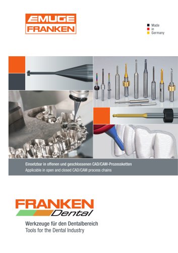 FRANKEN Dental Tools
80 Pages
 FRANKEN-CIMT Dental Tools
24 Pages
 Dental tools News 2021
20 Pages
 Micro
Micro32 Pages
 FIBER-cut
28 Pages
 Milling Technology
440 Pages
 Catalogue 520
672 Pages
 Thread Gauging Technology
104 Pages