SUBMINIATURE
1 /72Pages

SUBMINIATURE
1 /72Pages
Catalog excerpts
SUBMINIATUR SUBMINIATURE
Open the catalog to page 1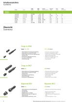
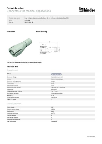
Seite Schutzart Spannung Page Degree of protection Voltage Snap-in IP40Serie 719 • 709 • Steckverbinder mit Schnappverriegelung • Steckverbinder umspritzt am Kabel • Ausfuhrungen mit und ohne Zugentlastung • Durchmesser oder Breite nur 9 mm • Einfache Montage 719 • 709 Series • Connectors with snap-in locking • Connectors moulded on cable • Versions with and without strain relief • Diameter or breadth only 9 mm • Easy assembly • Connectors with snap-in locking • Connectors moulded on cable • Internal strain relief • Easy assembly • Versions with colour-coding Serie 620 • Steckverbinder mit Schnappverriegelung...
Open the catalog to page 2
• Connectors with quick bayonet locking • Cable outlet in 2 sizes • Cable housing with integrated strain relief Bajonett IP40 Serie 710 • Steckverbinder mit schneller Bajonett-Verriegelung • Kabelverschraubung mit integrierter Zugentlastung Push-Pull IP67Serie 430 • Steckverbinder mit Push-Pull Verriegelung • Schirmbare Kabelsteckverbinder mit sehr guten EMV-Eigenschaften • Connectors with push-pull locking • Shielded cable connectors with excellent EMC protection • Pressing screw with immunity to vibration • Connectors with screw locking • Cable outlet in 2 sizes • Cable housing with integrated...
Open the catalog to page 3
Subminiatur Subminiature
Open the catalog to page 4
Snap-in IP40 SubminiaturSnap-in IP40 SubminiatureKabelsteckverbinder • Snap-in-Verriegelung • Am Kabel angespritzte Ausfuhrungen • Einfache Montage Cable Connectors • Snap-in locking system • Solder termination • Moulded versions • Easy assembly Panel Mount Connectors • Snap-in locking system • Solder/dip solder termination 11 Erlauterung der Schutzarten siehe technische Informationen./ 11 Explanation of protection standards see technic
Open the catalog to page 5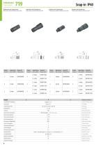
Snap-in IP40 Kabelstecker ohne Zugentlastung Male cable connector without strain relief Kabelstecker mit Zugentlastung Male cable connector with strain relief Kabeldose ohne Zugentlastung Female cable connector without strain relief Kabeldose mit Zugentlastung Female cable connector with strain relief
Open the catalog to page 6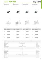
Subminiatur 7AASubminiature #19 * #09 Flanschstecker Lotanschluss Male panel mount connector, solder termination FlanschsteckerTauchlotanschluss Male panel mount connector, dipsoldertermination Flanschdose Lotanschluss Female panel mount connector, solder termination Flanschdose Tauchlotanschluss Female panel mount connector, dipsoldertermination
Open the catalog to page 7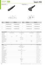
Snap-in IP40 Kabelstecker umspritzt Male cable connector moulded 11 Vergleichbare AWG Leiter siehe technische Informationen./ 11 Comparable AWG conductors see technical information.
Open the catalog to page 8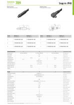
Snap-in IP40 Kabeldose umspritzt Female cable connector moulded Winkeldose umspritzt Female angled connector moulded ~ 31 L 11 Vergleichbare AWG Leiter siehe technische Informationen./ 11 Comparable AWG conductors see technical information.
Open the catalog to page 9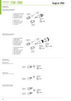
Subminiatur Subminiature Montageanleitung Assembly instruction Kabelsteckverbinder ohne Zugentlastung Cable connector without strain relief Kupplungshülse auf Kabel auffädeln. Kabel abmanteln auf L = 9 mm. Litzen abisolieren und anlöten. Kupplungshülse aufschrauben. Bead sleeve to cable. Dismantle cable to 9 mm length. Strip and solder single wires. Screw on sleeve. Buchseneinsatz female insert abisoli strip Kupplungshülse sleeve 0,2 Nm Steckereinsatz male insert Kabelsteckverbinder mit Zugentlastung Cable connector with strain relief 1. Druckschraube und Klemmhülse auf Kabel auffädeln. 2. Kabel...
Open the catalog to page 10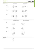
Contact arrangements Stifteinsatz (Steckseite) Buchseneinsatz (Steckseite) Male insert (mating side) Female insert (mating side) Bohrbilder Stifteinsatz (Leiterplatte) Bohrbilder Buchseneinsatz (Leiterplatte) Drilling schemes male insert (PCB) Drilling schemes female insert (PCB)
Open the catalog to page 11
Subminiatur Subminiature
Open the catalog to page 12
Snap-in IP67 SubminiaturSnap-in IP67 SubminiatureKabelsteckverbinder • Snap-in-Verriegelung • Am Kabel angespritzte Ausfuhrungen • Farbige Ausfuhrungen Cable Connectors • Snap-in locking system • Solder termination • Moulded versions • Coloured versions • Farbige Ausfuhrungen Panel Mount Connectors • Snap-in locking system • Solder/dip solder termination • Coloured versions 11 Erlauterung der Schutzarten siehe technische Informationen./ 11 Explanation of protection standards s
Open the catalog to page 13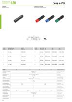
Snap-in IP67 Kabelstecker Male cable connector
Open the catalog to page 14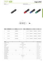
Female cable connector
Open the catalog to page 15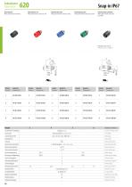
Flanschstecker Flanschstecker, rot Flanschstecker, blau Flanschstecker, grim Flanschstecker, tauchloten Male panel mount connector Male panel mount connector, red Male panel mount connector, blue Male panel mount connector, green Male panel mount connector, Bohrbilder siehe Seite 20 Drilling schemes see page 20
Open the catalog to page 16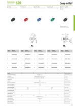
Flanschdose Flanschdose, rot Flanschdose, blau Flanschdose, grim Flanschdose, tauchloten Female panel mount connector Female panel mount connector, red Female panel mount connector, blue Female panel mount connector, green Female panel mount connector, Bohrbilder siehe Seite 20 Drilling schemes see page 20
Open the catalog to page 17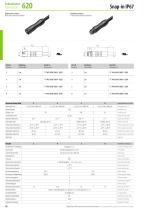
Snap-in IP67 Kabelsteckerumspritzt Male cable connector moulded Kabeldose umspritzt Female cable connector moulded 9,2 Polzahl Kabellange Bestell-Nr. Contacts Cable length Ordering-No. 11 Vergleichbare AWG Leiter siehe technische Informationen./ 11 Comparable AWG conductors see technical informat
Open the catalog to page 18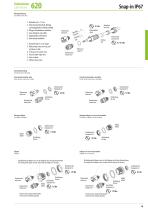
Subminiatur Subminiature Montageanleitung Assembly instruction 1. Abmanteln auf L = 12 mm. 2. Druckschraube, Klemmkorb, Dichtring und Kupplungshülse auf Kabel auffädeln. 3. O-Ring auf Kontakteinsatz aufziehen. 4. Litzen abisolieren und anlöten. 5. Kupplungshülse aufschrauben. 6. Druckschraube festdrehen. Klemmkorb pinch ring 0,5 Nm Steckereinsatz male insert 1. Dismantle cable to 12 mm length. 2. Bead pressing screw, pinch ring, seal and sleeve to cable. 3. Fit O-ring on the contact insert. 4. Strip and solder single wires. 5. Screw on sleeve. 6. Tighten pressing screw. 12 nteln abma tle n disma...
Open the catalog to page 19All Franz Binder GmbH & Co. Elektrische Bauelemente KG catalogs and technical brochures
 FOOD AND BEVERAGE
12 Pages
 HIGHLIGHTS '25
9 Pages
 SPLITTER
16 Pages
 POWER
POWER16 Pages
 MEDICAL TECHNOLOGY
40 Pages
 M5
M516 Pages
 INDUSTRY 4.0
20 Pages
 M8-D
M8-D20 Pages
 HEC
HEC24 Pages
 PRODUCT PORTFOLIO
28 Pages
 CATALOGUE
858 Pages
 POWER
POWER72 Pages
 MINIATURE
172 Pages