- Catalogs
- FSP Power Solution GmbH
- PB SERIES
PB SERIES
1 /3Pages

PB SERIES
1 /3Pages
Catalog excerpts
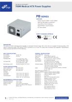
TECHNICAL DATASHEET FEATURES • Design meet IEC 60601-1 & IEC 62368-1 • Meet intel x86 platform requirement • Meet 80PLUS GOLD efficiency • Meet EN 55011 class B emission DESCRIPTION This series of AC/DC switching power supplies in a standard ATX form factor 165 x 150 x 86 mm is capable of delivering 600 or 700 watts of continuous power. PSU build-in DC/DC converter at +3.3V and +5V output rails to enhance load regulation. High-efficiency design complies with 80PLUS GOLD efficiency. GENERAL SPECIFICATIONS Input voltage: Input frequency: Input current: FSP600M-70PB Earth leakage current: 300 ^Amax. @ 264 VAC, 63 Hz Turn-on delay time Power factor: Efficiency: Hold-up time: Line regulation: Inrush current: Withstand voltage: OUTPUT SPECIFICATIONS Output voltage/current: Maxi. output power: 0.9 mini. @ 20% load mini. 17 mSminimumat 115VAC & 230VAC ±1% maximum at full load 50 A @115 VAC at 25C cold start 100 A @ 230 VAC at 25C cold start 4000 VAC from input to output (2 MOPP) 1500 VAC from input to ground (1 MOPP) 1500 VAC from output to ground 150,000 hours at full load & 25°C ambient, calculated ENVIRONMENTAL SPECIFICATIONS Operating temperature: Storage temperature: Relative humidity: Derating: Derate from 100% at +50°C linearly to EN55011:/ EN55032 Class B conducted, Class B radiated FCC / VCCI: Class B conducted, Class B radiated EN61000-3-2: Harmonic distortion, Class A EN61000-4-5: Surge, ±1 KVdiff., ±2 KVcom. EN61000-4-6: Conducted immunity, 3-6 Vrms EN61000-4-8: Magnetic field immunity, 30 A/m 30% reduction for 500 ms, 60% reduction for 100 ms >95% reduction for 10 ms ©2022 FSP Group. All Rights Reserved. All trademarks are registered to their respective owners.fm,
Open the catalog to page 1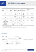
TECHNICAL DATASHEET 1. -5V is not for standard model but upon request. 2. Ripple and noise measurements shall be made under all specified load conditions through a single pole low pass filter with 20MHz cutoff frequency. Outputs shall bypassed at the connector with a 0.1uF ceramic disk capacitor and a 10uF electrolytic capacitor to simulate system loading. 3. The duration of peak power is less than 10 mS. 2. T2 : POWERGOOD DELAY TIME 100 ~ 500 mS 3. T3 : POWER FAIL DELAY TIME > 1 mS ©2022 FSP Group. All Rights Reserved. All trademarks are registered to their respective owners.
Open the catalog to page 2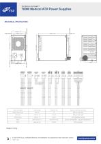
TECHNICAL DATASHEET Output connectors ©2022 FSP Group. All Rights Reserved. All trademarks are registered to their respective owners.
Open the catalog to page 3