- Catalogs
- HANNA Instruments
- edge® pH•EC•DO
edge® pH•EC•DO
1 /76Pages

edge® pH•EC•DO
1 /76Pages
Catalog excerpts
INSTRUCTION MANUAL
Open the catalog to page 1
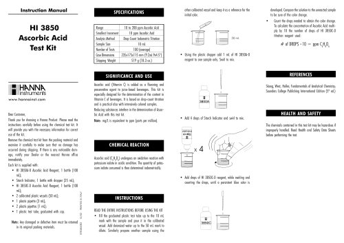
Dear Customer, Thank you for choosing a Hanna Instruments product. Please read this instruction manual carefully before using the instrument. This manual will provide you with the necessary information for correct use of the instrument, as well as a precise idea of its versatility. If you need additional technical information, do not hesitate to e‑mail us at [email protected] or view our worldwide contact list at www.hannainst.com. All rights are reserved. Reproduction in whole or in part is prohibited without the written consent of the copyright owner, Hanna Instruments Inc., Woonsocket, Rhode...
Open the catalog to page 2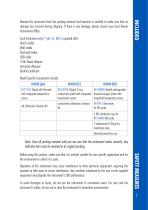
Remove the instrument from the packing material and examine it carefully to make sure that no damage has occurred during shipping. If there is any damage, please contact your local Hanna Instruments Office. Each instrument edge® (pH, EC, DO) is supplied with: Bench cradle Wall cradle Electrode holder USB cable 5 Vdc Power Adapter Instruction Manual Quality Certificate Model Specific Components include: Note: Save all packing material until you are sure that the instrument works correctly. Any defective item must be returned in its original packing. Before using this product, make sure that it...
Open the catalog to page 5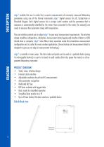
DIAGRAM DESCRIPTION edge® enables the user to make fast, accurate measurements of commonly measured laboratory parameters using one of the Hanna Instruments edge® digital sensors for pH, Conductivity or Dissolved Oxygen. Each digital sensors has a unique serial number and the parameter that is measures is automatically identified by the meter. Once connected to the meter, the sensor(s) are ready to measure their parameter along with temperature. The user interface permits you to adapt edge® to your exact measurement requirements. The intuitive design simplifies configuration, calibration, measurement,...
Open the catalog to page 6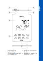
DIAGRAM HNSINk CONDITION RESPONSE POOR OOOD SLOW M ST gg (T) q © CD EDedge 1. Liquid Crystal Display (LCD) 2. Capacitive Touch Keypad 3. 3 mm jack input for edge® digital probes 4. Top mounted ON/OFF button 5. Micro USB device connection for power or PC interface 6. Standard USB host connection for data transfer to a USB thumb-drive
Open the catalog to page 7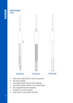
PROBE DIAGRAM Probes • Probes process signal directly for noise free measurements • Auto sensor recognition • Store calibration specific data from the last calibration • Are built with materials suitable for use in chemical analysis • Have integrated temperature measurement • Incorporate a 3 mm jack termination • Unique serial ID in every probe for traceability
Open the catalog to page 8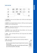
KEYPAD FUNCTION DIAGRAM 1. CAL/MODIFY - Used to enter and exit calibration mode. In SETUP, used to initiate changes of a configuration setting. 2. GLP/CFM - Used to display GLP calibration information. In SETUP, used to confirm change made. In calibration, used to accept calibration points. 3. RANGE/u - Used to select measurement range. In SETUP, used to move to right in pick list. In log RCL, used to view GLP data for a data point. 4. SETUP/CLR - Used to enter/exit SETUP mode. During calibration, used to clear previous calibration data. In log RCL, used to clear log records. 5. ^/^ - Used to...
Open the catalog to page 9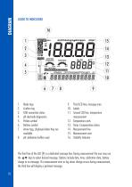
9. Third LCD line, message area 11. Second LCD line, temperature measurement 13. Temp. Compensation status 7. Arrow tags, displayed when they are available 8. pH calibration buffers used The third line of the LCD (9) is a dedicated message line. During measurement the user may use the ^ ^ keys to select desired message. Options include date, time, calibration data, battery charge or no message. If a measurement error or log status change occurs during measurement, the third line will display a pertinent message.
Open the catalog to page 10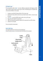
The main operating modes of edge ® are setup, calibration, measurement, data logging, and data export. Follow this general outline of steps to get you started. The following topics are expanded upon in the sections that follow in this manual. 1. Familiarize yourself with the design features of this unique meter. 2. Decide how the meter will be used and set up the wall or bench cradle in a clean area near line power. 3. Turn edge ® on using the ON/OFF button located on the top of the meter. 4. Plug in the probe required for measurement. 5. SETUP the measurement parameters required for the measurement...
Open the catalog to page 11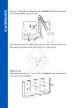
Slide edge ® into the cradle while positioning the probe cable behind the cradle. Put the probe/sensor into the electrode holder and secure cable in clips. Connect the power adapter cable to the rear socket of the bench cradle. Connect the other end to the power adapter and plug into line power. Verify the battery icon indicates charging. Wall Cradle Setup Choose suitable wall location. (Use 2.5 mm or US #3 bit). Fasten the wall cradle using the provided screws. Snap cover over screw heads.
Open the catalog to page 12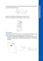
Connect the 3 mm probe jack to the socket located at the bottom of edge ®. Slide edge ® into the wall cradle. Verify the battery icon indicates charging. Connect the power adapter cable to the bottom socket of the wall cradle. Connect the other end to the power adapter and plug into line power. Power Connection Alternatively to using the cradle for power, edge ® can be powered by micro USB socket at the top. Plug the 5 VDC adapter into the power supply socket or by connecting directly to a PC. Note: edge ® is supplied with a rechargeable battery inside, which provides about 8 hours of continuous...
Open the catalog to page 13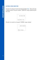
ELECTRODE & PROBE CONNECTIONS Connect the 3 mm probe jack to the probe input located on the bottom of edge ®. Make sure the probe is completely connected. If the probe is recognized, “CONNECTING” message is displayed along with sensor model. If the probe is not connected or not recognized, “NO PROBE” message is displaye
Open the catalog to page 14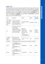
GENERAL SETUP The following General Setup options are displayed regardless of the sensor being used. These settings remain when switching to another probe type or when no probe is attached. Options are tabulated in the table below with choices and default values. Options are accessed by pressing SETUP/CLR key. Loop through the options by using the ^ ^ keys. To modify a setting, press CAL/MODIFY key. The option may be modified by using RANGE/u, ^ and ^ keys. Press GLP/CFM key to confirm the change. To exit SETUP press SETUP/CLR key.
Open the catalog to page 15All HANNA Instruments catalogs and technical brochures

Archived catalogs
 HI 9125N Portable pH Meter
4 Pages
 HI84500
6 Pages
 HI84502
6 Pages
 General Catalog
772 Pages
 HI99151
4 Pages
 HI99191
4 Pages
 edge® dedicated Brochure
8 Pages
 Professional Waterproof Meters
12 Pages
 HI2202 edge blu
8 Pages
 HI5000 Series Benchtop Meters
12 Pages
 Hanna Titration Catalog
40 Pages
 edge pH EC DO Brochure
8 Pages
 HI4114
9 Pages
 HI98129
2 Pages


- Detection kit
- Solvent reagent
- Laboratory reagent
- Thermometer
- Optical test kit
- Dye reagent kit
- Digital thermometer
- Buffer solution reagent
- Quality control reagent
- Laboratory testing system
- Temperature sensor
- Straight electrode
- Research detection kit
- Electrolyte reagent
- Gas sensor
- Spectrophotometer
- Probe thermometer
- Waterproof thermometer
- Laboratory sensor
- PH reagent