Mini hydraulic power pack type A (2025)
1 /26Pages

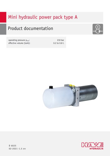
Mini hydraulic power pack type A (2025)
1 /26Pages
Catalog excerpts
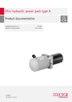
operating pressure pmax: 210 bar effective volume (tank): 0.2 to 0.8 l
Open the catalog to page 1
© by HAWE Hydraulik SE. The reproduction and distribution of this document, as well as the use and communication of its contents to others without explicit authorization, is prohibited. Offenders will be held liable for the payment of damages. All rights reserved in the event of patent or utility model applications. Brand names, product names and trademarks are not specifically indicated. In particular with regard to registered and protected names and trademarks, usage is subject to legal provisions. HAWE Hydraulik respects these legal provisions in all cases. HAWE Hydraulik cannot provide individual...
Open the catalog to page 2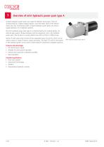
Compact hydraulic power packs are a type of hydraulic power pack. They are characterised by a highly compact design, since the motor shaft of the electric motor also acts as the pump shaft. Compact hydraulic power packs are used to supply hydraulic oil in hydraulic systems. The mini hydraulic power pack type A is characterised by its modular design. An external gear pump is flange-mounted onto the equipment rack in the hydraulic power pack. The oil tank is a round, plastic tank with an M14x1.5 filling screw. Version A 100 comes with a choice of two equipment racks (Q and H), which can be used...
Open the catalog to page 4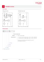
Available versions One flow direction (Q) Circuit symbol Lifting version (H) Ordering exampleA 100 H 1 A F2E 1 1 /... A 065 Q 2 A C2D /... Throttle 1 ■ 1: Return throttle Q3D00 Lowering valve 1 ■ 1: Lowering valve 2/2-poppet bypass valve 24 V (DC) = SP32 CMD ■ 2: Lowering valve 2/2-poppet bypass valve 12 V (DC) = SP32 CME Throttle valve and lowering valve required for version H; not available for version Q 2.1 "Basic type and size"
Open the catalog to page 5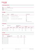
A 065 exclusively with DC motor H A 100 Lifting version, with DC motor Q A 065 one flow direction, with DC motor A 100 one flow direction, with DC or single-phase-motor 2.3 Tank size Coding
Open the catalog to page 6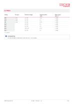
2.5 Motor Coding For type Nominal voltage For A4D and B2D: Combination with tank size 1 not possible.
Open the catalog to page 7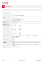
Installation position A 065 Vertical (tank on top) A 100 Horizontal or vertical (tank on top) Attachment ■ firmly screwed ■ A 065: 2x M5 on the equipment rack A 080, A 100: 2x M6 on the equipment rack ■ preferably elastic suspension Pump design Typical noise level (distance 1 m, decoupled attachment) External gear pump Motor Hydraulic fluid Hydraulic fluid, according to DIN 51 524 Parts 1 to 3; ISO VG 10 to 68 according to DIN ISO 3448 Viscosity range: 10 - 500 mm2/s Other media on request Temperatures ■ A 065: Environment: approx. -15 to +80°C, hydraulic fluid: -10 to +40°C, ensure the correct...
Open the catalog to page 8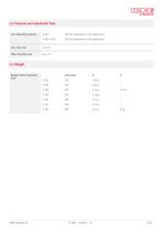
Weight without hydraulic fluid A 065 A 080 A 100 A 100 A 100 A 100 A 100
Open the catalog to page 9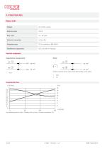
Nominal power Duty cycle Electrical connection Protection class Interference suppression IP 50 according to DIN 40050 2L3C (variants on request) Terminal assignment Temperature measurement Rotation direction of the motor shaft: left (looking at the shaft)
Open the catalog to page 10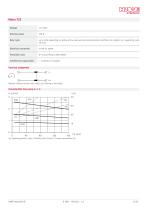
Duty cycle up to 40% depending on delivery flow, pressure and environmental conditions (in relation to 1 operating cycle Electrical connection 2x M6 for eyelet Protection class IP 54 according to DIN 40050 Interference suppression -- (variants on request) Rotation direction of the motor shaft: left (looking at the shaft)
Open the catalog to page 11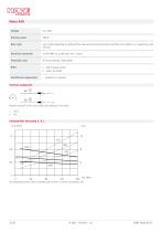
Duty cycle up to 40% depending on delivery flow, pressure and environmental conditions (in relation to 1 operating cycle Electrical connection 2x flex AWG 16 (1100 mm) red +, black - Protection class IP 50 according to DIN 40050 Other ■ with thermal switch Interference suppression -- (variants on request) Rotation direction of the motor shaft: left (looking at the shaft)
Open the catalog to page 12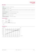
Motor A2D Voltage 24 V direct current Duty cycle up to 30% depending on delivery flow, pressure and environmental conditions (in relation to 1 operating cycle Electrical connection 2x flex AWG 18 (500 mm) red +, black - Protection class IP 54 according to DIN 40050 Other motor U L-listed Interference suppression 2L3C (variants on request) Rotation direction of the motor shaft: left (looking at the shaft)
Open the catalog to page 13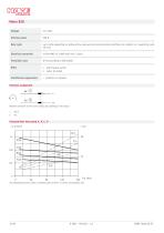
Nominal power Duty cycle Electrical connection Protection class Other Interference suppression Terminal assignment up to 40% depending on delivery flow, pressure and environmental conditions (in relation to 1 operating cycle 10 min) 2x flex AWG 16 (1000 mm) red +, black -IP 50 according to DIN 40050 ■ with thermal switch Rotation direction of the motor shaft: left (looking at the shaft) Characteristic line pump A, B, C, D
Open the catalog to page 14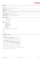
Nominal power Duty cycle up to 40% depending on delivery ow, pressure and environmental conditions (in relation to 1 operating cycle 10 min) Electrical connection cables with ferrules Protection class Terminal assignment Rotation direction of the motor shaft: left (looking at the shaft) 1 2 3 4 brown black blue yellow/green Characteristic line pump A, B Sp operating pressure (bar); Q delivery ow (l/min)
Open the catalog to page 15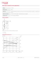
Sp operating pressure (bar); Q delivery flow (l/min); I current consumption (A)
Open the catalog to page 16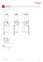
Dimensions AH dimensions in mm, subject to change. Coding Tank size L
Open the catalog to page 17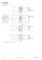
hydraulic connections P and T = plug connection
Open the catalog to page 18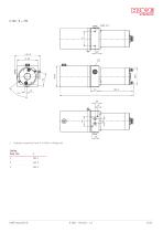
A 100 - Q ... F2E 1 hydraulic connections P and T: 2x M10x1 or flange port Coding Tank size 1
Open the catalog to page 19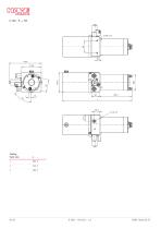
A 100 - H ... F2E Coding Tank size
Open the catalog to page 20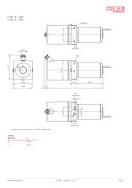
A 100 - Q ... A4D A 100 - Q ... B2D 1 hydraulic connections P and T: 2x M10x1 or flange port
Open the catalog to page 21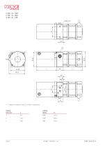
1 hydraulic connections P and T: 2x M10x1 or flange port
Open the catalog to page 22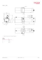
hydraulic connections P and T: 2x M10x1 or ange port Coding Tank size
Open the catalog to page 23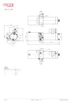
Coding Tank size
Open the catalog to page 24
Installation, operation and maintenance information O NOTICE Reference to other document Assembly instructions for mini hydraulic power pack type A: B 6025 Available for this product: assembly instructions with notes on
Open the catalog to page 25
HAWE Micro Fluid GmbH Borsigstraße 11 | 93092 Barbing | Germany Phone +49 89 379100-6000 | [email protected] | www.hawe.com hawe.com/contact
Open the catalog to page 26All HAWE catalogs and technical brochures
 HR 050
15 Pages
 HAWE compact
72 Pages

Archived catalogs
 Product overview
65 Pages
 Mini hydraulic power pack type A
16 Pages
 Compact power unit CPU
2 Pages
 Floor-Lock-Sets
4 Pages