Valve bank (directional seated valve) type TLC 3
1 /15Pages

Valve bank (directional seated valve) type TLC 3
1 /15Pages
Catalog excerpts
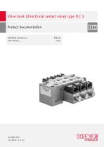
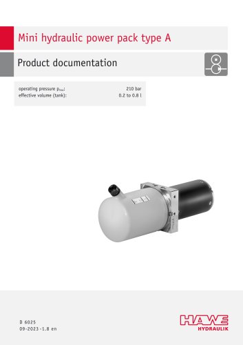
Valve bank (directional seated valve) type TLC 3 Product documentation Operating pressure pmax: Flow rate Qmax:
Open the catalog to page 1
© by HAWE Hydraulik SE. The reproduction and distribution of this document as well as the use and communication of its contents to others without explicit authorization is prohibited. Offenders will be held liable for the payment of damages. All rights reserved in the event of patent or utility model applications. Brand names, product names and trademarks are not specifically indicated. In particular with regard to registered and protected names and trademarks, usage is subject to legal provisions. HAWE Hydraulik respects these legal provisions in all cases. HAWE Hydraulik cannot provide individual...
Open the catalog to page 2
Overview of TLC 3 valve bank The directional spool valve type TLC is a combined design consisting of a directional spool valve and a releasable check valve. It can be used to hold hydraulic actuators in position for long periods of time. The built-in T-throttles allow the user to preset the speed of the actuators. The magnetic plugs used are IP65 connectors (AMP superseal) used in the automotive industry. Multiple directional valves can be combined in series in the valve bank type TLC. Combined with the compact hydraulic power pack type A10, this forms a minihydraulics system solution that requires...
Open the catalog to page 4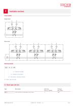
Available versions Circuit symbol Single block Valve bank 2.3 "Number of functions" 2.2 "Inlet block, connection block" 2.1 "Basic type and size" 2.1 Basic type and size Type Flow rate QA/B max (l/min) with throttle and releasable check valves
Open the catalog to page 5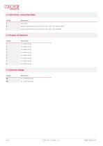
2.2 Inlet block, connection block Coding inlet plate adapter plate (hydraulic power pack A with motor F2E, A4B and R2E) adapter plate (hydraulic power pack A with motor A4D and B2D) 2.3 Number of functions Coding 2.4 Solenoid voltage Coding
Open the catalog to page 6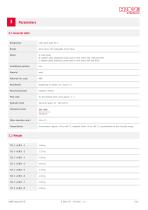
3.1 General data Designation valve bank type TLC 3 spool valve with releasable check valves A: inlet plate B: adapter plate (hydraulic power pack A with motor F2E, A4B and R2E) C: adapter plate (hydraulic power pack A with motor A4D and B2D) Installation position depending on design see Chapter 4.1 Pilot ratio for the piloted check valve approx. 7 : 1 Hydraulic uid Cleanliness level Filter retention rate β Environment: approx. -30 to +80 °C, hydraulic uid: -25 to +80 °C, pay attention to the viscosity range.
Open the catalog to page 7
3.3 Pressure and volumetric ow Max. operating pressure 3.4 Characteristic lines Pressure drop curve HAWE Hydra
Open the catalog to page 8
3.5 Electrical data Nominal voltage Nominal power Nominal current Switching voltage (at T < +40 °C and Q < 1 l/min) Varistor (in plug housing) Relative duty cycle depending on environment, up to 100% duty cycle Excitation winding Solenoid connection AMP Superseal 1,5 plug, line cross section 0,3 - 1,5 mm² Coil body material
Open the catalog to page 9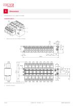
All dimensions in mm, subject to change. Connection plate A Adjusting screw for return throttle (T-throttle) Connection plate A: Hose connections (TLC 3-A) 2 Electrical connection
Open the catalog to page 10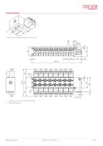
Connection plate B: Wide equipment racks (TLC 3-B) Adjusting screw for return throttle (T-throttle) Electrical connection
Open the catalog to page 11
Connection plate C: Narrow equipment racks Connection plate C: Narrow equipment racks (TLC 3-C) 1 2 Adjusting screw for return throttle (T-throttle) Electrical connection
Open the catalog to page 12
Installation, operation and maintenance information Observe the document B 5488 “General operating instructions for assembly, commissioning, and maintenance.” 5.1 Intended use This product is intended exclusively for hydraulic applications (uid technology). The user must observe the safety measures and warnings in this document. Essential requirements for the product to function correctly and safely: All information in this documentation must be observed. This applies in particular to all safety measures and warnings. The product must only be assembled and put into operation by specialist personnel....
Open the catalog to page 13
Electrical and hydraulic connection DAMAGE Only use suitable ttings 1. 2. 3. 4. 5. Space required for assembly, installation and commissioning: 500 x 100 x 250 mm (WxHxD). Place the product in position in the higher-level machine. Ensure that all the fastening bores and hydraulic connections align correctly. Tighten the hydraulic connections and fastening screws of the valve bank correctly. Connect the electromagnetic valves to the control system: NOTE It is not permitted to actuate more than one solenoid per valve unit at the same time (function of the TLC 3). AMP Superseal 1.5 plug, conductor...
Open the catalog to page 14
HAWE Micro Fluid GmbH Borsigstraße 11 | 93092 Barbing | Germany Phone +49 89 379100-6000 | [email protected] | www.hawe.com hawe.com/contact
Open the catalog to page 15All HAWE catalogs and technical brochures
 HR 050
15 Pages
 HAWE compact
72 Pages
Archived catalogs
 Product overview
65 Pages
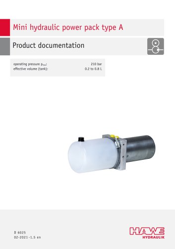 Mini hydraulic power pack type A
16 Pages
 Compact power unit CPU
2 Pages
 Floor-Lock-Sets
4 Pages