- Company
- Products
- Catalogs
- News & Trends
- Exhibitions
C-TOP S
1 /4Pages
C-TOP S
1 /4Pages
Catalog excerpts

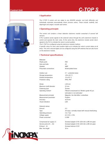
Control Unit I Application The C-TOP S control unit can adapt to any INOXPA actuator, and both efficiently and individually automate pneumatically driven process valves. These include: butterfly, ball, diaphragm and single or double seat valves. I Operating principle The control unit contains a linear detection electronic module comprised of several hall sensors. A PLC systems sends signals to the solenoid valves through the unit’s electronic module to control and operate the main valve. At the same time, the electronic module sends return signals to the PLC to indicate the valve’s current position. The C-TOP S is configured using the electronic module’s buttons. A specific colour for each valve position lights up to indicate the valve’s current status at all times. The unit’s coloured lights can be configured using the DIP switches that are also found on the electronic module. Materials: Plastic parts Nuts and bolts Gaskets Pneumatic connections Storage temperature Ambient temperature Protection rating Stroke Maximum shaft diameter Fastening type Operating medium Measurement principle Screws Filtered compressed air, filtration grade 40 μm, lubricated or non-lubricated Magnetic, the Hall effect, contactless Measurement parameter Accuracy Visual indicators Solenoid valves: Amount Type Operating pressure 0-3 3/2 ways, normally closed with manual interlocking 3 to 7 bar Voltage supply Power consumed Compressed air supply (1) Service ports (A1... A3) Exhaust (3) Max. line length Screwed adapter G1/8, QS-8 (for a Ø8 mm pipe) Screwed adapter G1/8, QS-6 (for a Ø6 mm pipe) Screwed
Open the catalog to page 1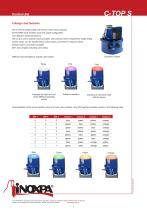
Control UnitI Design and features The C-TOP S installs easily onto the top of the valve’s actuator. AUTOTUNE mode enables quick and simple configuration. Line detection using hall sensors. Use of up to three solenoid valves possible. One solenoid valve is required for single-acting control valves, two for double-acting control valves, and three for mixproof valves. External sensor connection possible. 360° view of lights indicating valve status. Different coloured lights to indicate valve status: Indicates the start and end Indicates transition Indicates an electronic fault of the different operating...
Open the catalog to page 2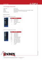
Control Unit124 V DC digital communication Voltage supply Outputs Terminal Main input External sensor input Push-in type, nominal cable section from 0.2 to 1.5 mm2 (22AWG to 16AWG) M16 stuffing gland x 1.5 (4 to 10 mm diameter cable) Electrical connections Version for up to 1 solenoid valve and 3 outputs Markingl Description Version for up to 3 solenoid valves and 4 outputs Markingl Description Ext - OV (GND) external sensor Ext + 24 V DC external sensor Ext S External sensor signal I 2 Input 2 (solenoid valve 2) I 1 Input 1 (solenoid valve 1)
Open the catalog to page 3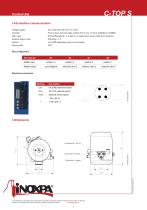
Control UnitI AS-interface communication Voltage supply Terminal Main input External sensor input Slave profile Push-in type, nominal cable section from 0.2 to 1.5 mm2 (22AWG to 16AWG) M16 stuffing gland x 1.5 with a 2 m cable and a 4 pole male M12 connector M16 plug x 1.5 Bits configuration Master input position 4 position 3 position 2 position 1 Master output not configured solenoid valve 3 solenoid valve 2 solenoid valve 1 Ext - 0V (GND) external sensor Ext + 24 V DC external sensor Ext S External sensor s ignal The information is for guidance only. We reserve the right to modify any material...
Open the catalog to page 4All INOXPA catalogs and technical brochures
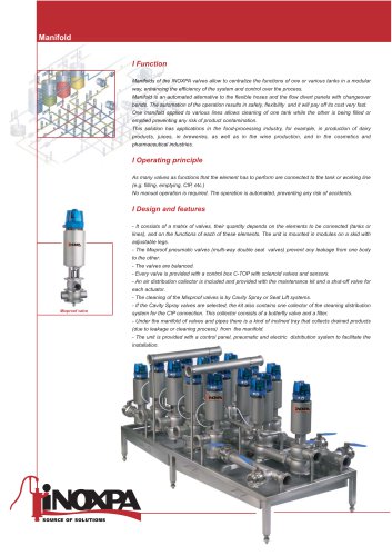 Manifold
3 Pages
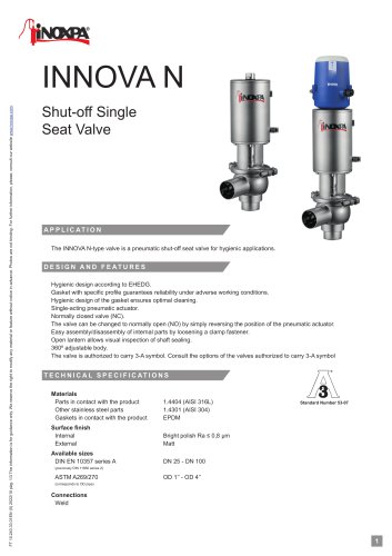 INNOVA N
3 Pages
 INNOVA K
4 Pages
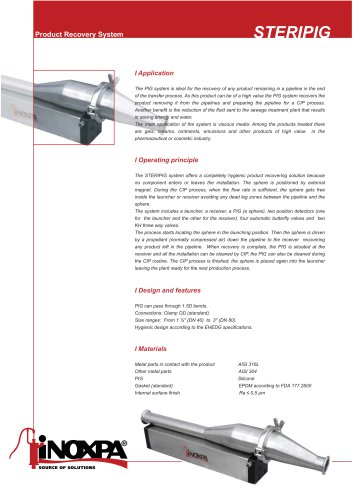 STERIPIG
2 Pages
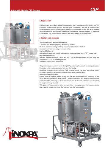 CIP
CIP3 Pages
 M-226
M-2264 Pages
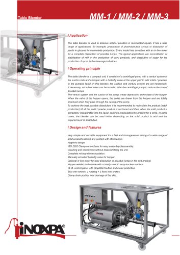 MM
MM3 Pages
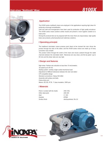 8100X
8100X2 Pages
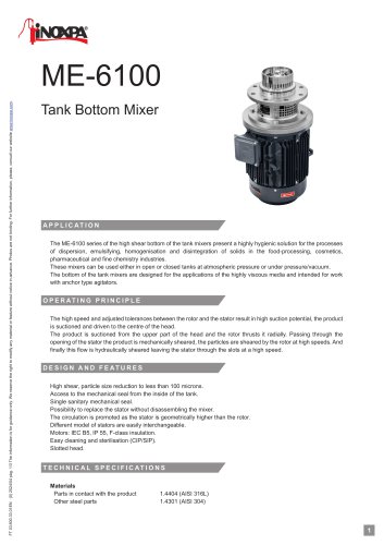 ME-6100
3 Pages
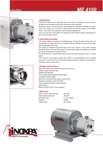 ME-4100
2 Pages
 Agitators for Standard Tanks
6 Pages
 NBI
NBI2 Pages
 81700 / 82700 / 83700
4 Pages
 7550
75502 Pages
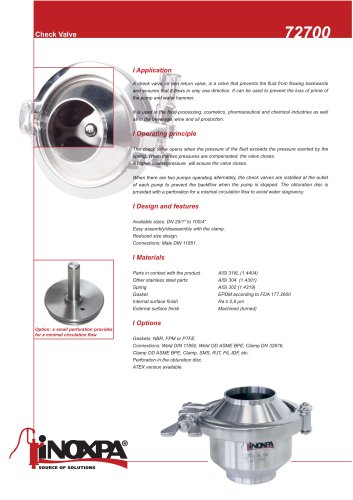 72700
727002 Pages
 A470
A4704 Pages
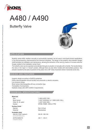 A480 / A490
5 Pages
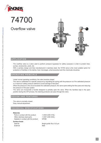 74700
747003 Pages
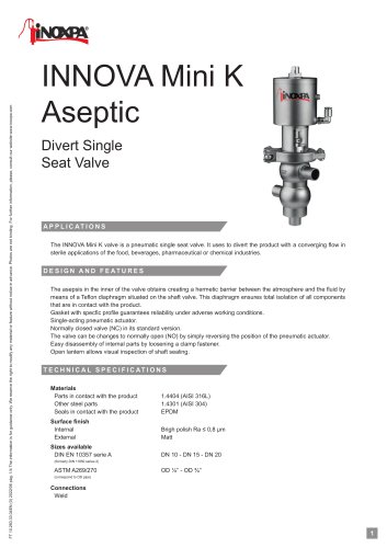 INNOVA Mini K
4 Pages
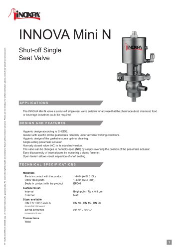 INNOVA Mini N
3 Pages
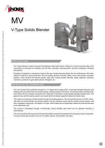 MV
MV5 Pages
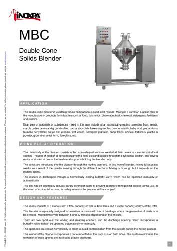 MBC
MBC4 Pages
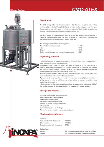 CMC-ATEX
3 Pages
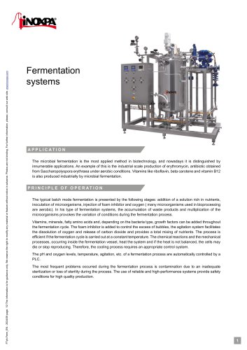 Fermentation systems
2 Pages
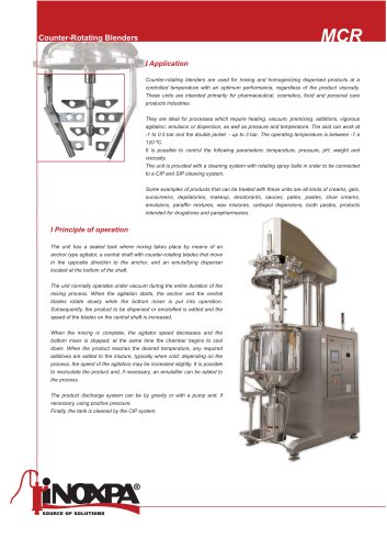 MCR
MCR14 Pages
 CXC
CXC2 Pages
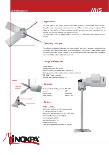 NHS
NHS2 Pages
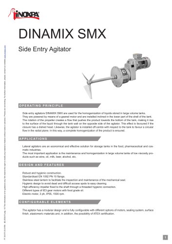 DINAMIX SMX
5 Pages
 BMA
BMA2 Pages
 MCR
MCR4 Pages
 Kiber KS
4 Pages
 DCS
DCS3 Pages
 DCH+
DCH+3 Pages
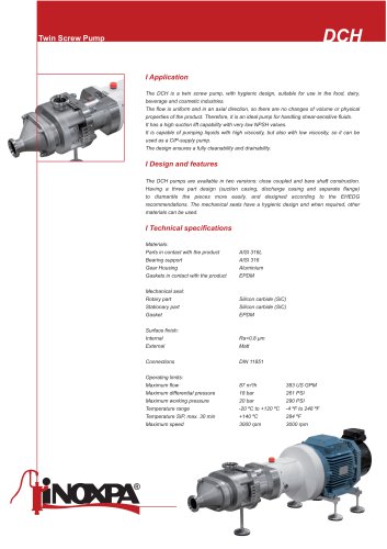 DCH
DCH3 Pages
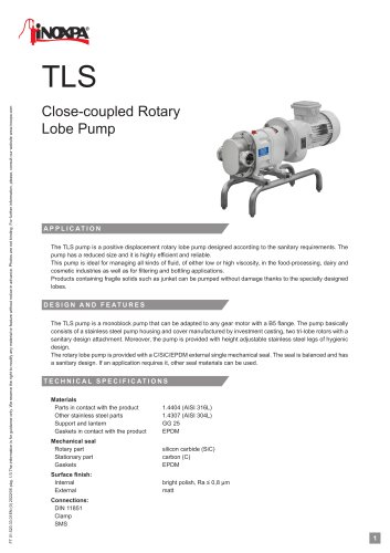 TLS
TLS3 Pages
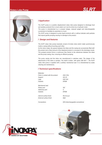 SLRT
SLRT2 Pages
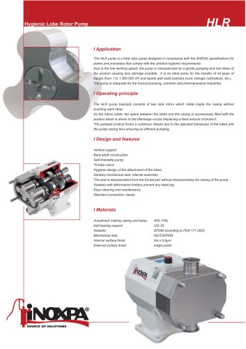 HLR
HLR2 Pages
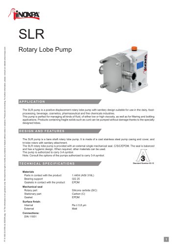 SLR
SLR4 Pages
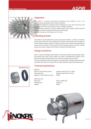 ASPIR
ASPIR5 Pages
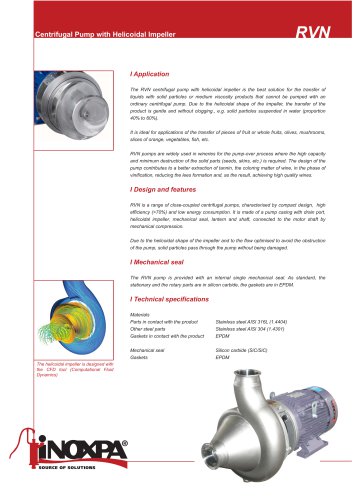 RVN
RVN3 Pages
 RV
RV2 Pages
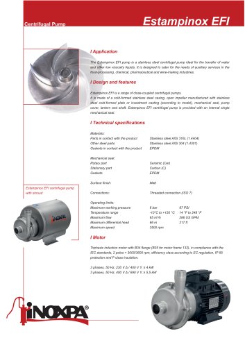 Estampinox EFI
4 Pages
 Hyginox SEN
3 Pages
 HYGINOX SE
5 Pages
 Prolac HCP SP
4 Pages
 PROLAC HCP WFI
2 Pages
 PROLAC HCP
5 Pages
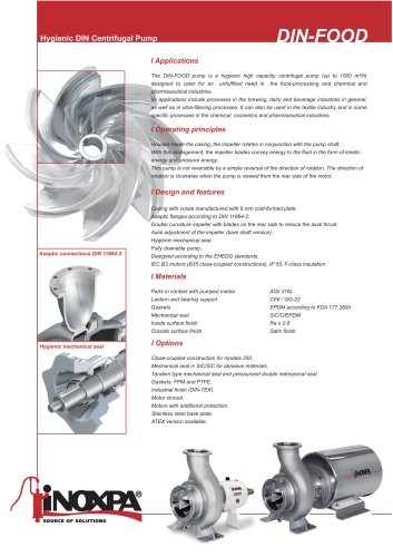 DIN-FOOD
2 Pages
 PHARMACY AND COSMETICS
10 Pages
 Angular filter
17 Pages
 BUTTERFLY AND BALL VALVES
4 Pages
 INNOVA SEAT VALVES
36 Pages
 FOOD INDUSTRY
10 Pages
- Agitator
- Benchtop agitator
- Medical filter
- Electronic stirrer
- Mixer
- Liquid pump
- Bioreactor
- Benchtop mixer
- Digital control unit
- Manifold
- Compact pump
- Industrial mixer
- Rotator mixer
- Check valve
- Microbial fermentation bioreactor
- Sample preparation mixer
- Mixer for the pharmaceutical industry
- Vacuum mixer
- Floor-standing mixer