MILD 3.0
1 /12Pages

MILD 3.0
1 /12Pages
Catalog excerpts
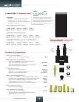
MILO 3.0mm 3.0mm Ø MILO® Implants with Application: • Prosthetic Connection: Ø 1.8 mm O-Ball • *Lengths: 10, 11.5, 13, 15 & 17 mm. • Surface treatment: Blasted + Progressively Acid Etched Titanium 3.0mm MILO® Fine Pitch Implants OSSEAN bio-active surface is found on all MILO implants. Its structure is engineered to increase host-to-implant biocompatibility and biomechanical response which is well documented in the scientific literature. 3.0mm MILO® Wide Pitch Implants 3.0mm MILO® Wide Pitch Implants, Long Collar (4mm) *The actual thread length is 2mm less than the catalog description, regardless...
Open the catalog to page 2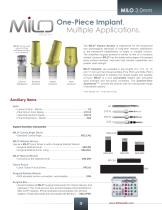
One-Piece Implant. Multiple Applications. The MILO® Implant System is engineered for the anatomical and physiological demands of long-term denture stabilization or the permanent rehabilitation of single or multiple incisors. The simplified surgical protocol is similar to that of a miniature implant, however, MILO® has the added advantages of increased bone surface interface, improved load transfer capabilities and greater yield strength. MILO® can be used with an O-Ring and Metal Housing or an abutment Denture Stabilization Standard Abutment Angled Abutment MILO® Implants* are available in five...
Open the catalog to page 3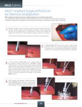
MILO Implant Surgical Protocol for Denture Stabilization ® Milo® Implant treatment planning, drilling sequence and implant placement. A comprehensive patient interview, medical /dental history and a complete oral examination should be conducted. Diagnostic radiographs and mounted study models, if appropriate, should also be obtained. Palpate the ridge in order to obtain a three-dimensional concept of the bone structure. Ridge calipers can be employed as needed. Clinical observation and the use of a dental probe is recommended to assess the quantity and quality of the soft tissue. CT Scan might...
Open the catalog to page 4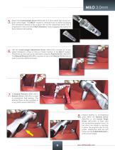
Attach the Contra-Angle Driver (MDLCAD) to a slow speed high torque surgical contra-angle. The MILO® Implant is removed from its sterile packaging and transferred directly to the surgical site via this attachment driver that is engineered to slip over the O-Ball Abutment, firmly engaging the implant for direct delivery and seating. Use the Contra-Angle Attachment Driver (MDLCAD) mounted on a slow speed handpiece (15rpm or less) to initiate insertion of the MILO® Implant. Placement by hand can be an alternative using the Ratchet Driver (MDLRD). The Manual Wrench (MDLMW) mounted on top of the Ratchet...
Open the catalog to page 5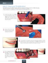
MILO Denture Stabilization ® Chairside Pick-up of the MILO® denture retentive component (O-Ring encased in a Metal Housing). Prior to the placement of implants, the patient’s denture should be stabilized. A reline procedure, an equilibration or a new denture may be fabricated if necessary. Transfer the position of the O-Balls to the tissue-bearing surface of the denture by marking the heads of the O-Balls with a soft lead pencil or capturing their impression by inserting a strip of soft silicone or soft wax inside the denture. Using a 5mm Ø resin bur, relieve the opening around the abutment impressions...
Open the catalog to page 6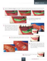
Remove the Retentive Housings. Punch holes in a rubber dam at each implant site and place the rubber dam over each abutment, leaving only the O-Ball heads exposed. Lubricate the O-Ball heads. These steps will prevent any acrylic lock-on. Snap a Retentive Housing Assembly (MDLMMH) over each O-Ball in preparation for final seating. Clean, wash and dry the denture. Fill the abutment recesses with selfcure resin. Paint a small amount of this material over each retentive housing. As soon as the acrylic in the denture becomes resistant to fl ow, seat the denture, keeping light, bilateral pressure on...
Open the catalog to page 7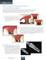
MILO Implant Surgical Protocol for Fixed Restorations ® All of the preliminary procedures that pertain to treatment planning, patient examination, gathering of diagnostic data and patient communication should be adhered to. The use of mounted diagnostic study models is strongly recommended. This will enable a preview of the maxilla and help to determine the most appropriate location and angulation of the osteotomy site. A Tissue Punch (RPCA3) is used to cut the soft tissue at the osteotomy site. When thin, porous or irregularly contoured bone is encountered, or when gingival manipulation or grafting...
Open the catalog to page 8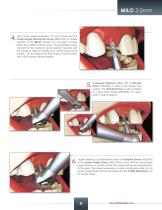
Use a slow speed handpiece (15 rpm or less) and the Contra-Angle Attachment Driver (MDLCAD) to initiate insertion of the MILO® Implant. Do not apply a torque higher than 35Ncm with the motor. The final higher torque required for final seating must be applied manually with the ratchet. It might be beneficial to use the Torque-Lock ratchet, (TL) to measure the final torque; a direct indica tion of the implant primary stability. A Surgical Ratchet (SRA) with a Ratchet Driver (MDLRD) is used to accomplish final seating. The Ratchet Driver is also available in a long shaft version (MDLRDL) for clearance...
Open the catalog to page 9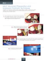
MILO Abutment Preparation and Impression Prosthetic Techniques ® The MILO® is an extremely versatile prosthetic system offering a straight, 15 degree and a plastic castable version. Abutments simply fit over the O-Ball assembly and convert the implant from removable to fixed prosthetic options. Once the placement of the implant has been accomplished, the prosthetic component of choice is now ready for use. In this instance, the final restoration will be made using the MILO® Straight Cement-Over Abutment (MLSA). A MILO® Pick-Up Impression Coping (MLT) is snapped over the O-Ball implant assembly....
Open the catalog to page 10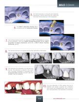
The final impression is removed and inspected. Examination should reveal that the coping will have been firmly picked up in the impression. The MILO® Laboratory Analog (MLA) is inserted into the Impression Coping. The working model is poured up. Appropriate MILO® Abutments are chosen for the restoration. They can be MILO® Straight Abutments (MLSA), MILO® Angulated 15 Degree Abutments (MLAA15) or MILO® Plastic Castable Abutments (MLPA). The selected abutment is prepared and the final restoration is fabricated. The abutment and restoration are returned from the lab. The abutment is placed in the...
Open the catalog to page 11All Intra-Lock International, Inc. catalogs and technical brochures
 Intra-Lock® Implants
29 Pages
 Gold&Blue
28 Pages
 Conic
Conic6 Pages
 Flatone
16 Pages
 MILD 3.75mm
2 Pages
 MDL 15°
4 Pages
 MDL
MDL6 Pages
 index
index72 Pages
 gold-and-blue
28 Pages
 L-PRF
L-PRF6 Pages
 Blossom
8 Pages
- Implant abutment
- Titanium implant abutment
- Straight implant abutment
- Dental surgery instrument kit
- Dental implant
- Titanium dental implant
- Benchtop centrifuge
- Internal implant abutment
- Straight dental implant
- Hexagonal implant abutment
- Screw implant abutment
- Internal hexagon implant abutment
- Dental implant analog
- Collection kit
- Straight dental implant analog
- Dental screwdriver
- Stainless steel dental implant analog
- Microtube centrifuge
- One-piece dental implant
- Blood collection kit