Catalog excerpts

Oinl juma eyou n^d. With us
Open the catalog to page 1
Data and images Intrauma S.p.A. reserves the right to make changes to the design and finish of the products shown and described in this catalogue without prior notice. The images are provided for information purposes only. The information displayed is purely indicative about some general features of the products shown herein. This information does not constitute in any way whatsoever a description of the specific features by the Manufacturer. Therefore, we recommend the customer to always contact the company Intrauma S.p.A. in order to obtain complete information on the specific features. ©...
Open the catalog to page 2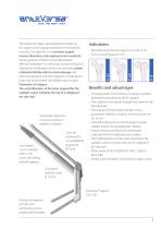
Two fixation elements to ensure maximum stability in rotation Clavo de antirrotación con estabilidad angular de Ø 5 mm Cannulated conical cephalic Ø 8/11 mm screw, self-drilling and self-tapping • Pertrochanteric fractures type 31-A1 and 31-A2 • Trans-cervical fractures 31-B The Anteversa® plate was developed considering the stages of the surgical procedure for trochanteric fractures. The objective is to minimize surgical trauma, blood loss, and response times in patients whose general conditions are predominantly affected. Anteversa® is a minimally invasive method of stabilization and...
Open the catalog to page 3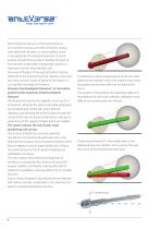
Pertrochanteric fractures of the proximal femur are common traumas, and internal fixation using a tube-plate with dynamic or intramedullary screw is recognized as the standard treatment. A recent analysis showed that success in treating this type of fracture with a tube-plate is statistically superior to treatment with an intramedullary nail. The result of fixation of the pertrochanteric fracture depends on the positioning of the cephalic screw and the most common mode of failure of this fixation is cut-out from the head of the femur. Intrauma has developed Anteversa®, an innovative system...
Open the catalog to page 4
Mechanical tests The state of tension that the Anteversa® support is able to bear before reaching the yield point is evaluated by the von Mises criteria (yield criterion). Mechanical tests allowed the definition of the high ductility of the support, which indicates the ability of the material to plastically deform under load before breaking, that is, the ability to withstand plastic deformation. The images below show, in various views, the areas of the Anteversa® support that are the most stressed during cyclic loading tests (load of 1000N). The areas highlighted in red represent the...
Open the catalog to page 5
Anteversa® procedure 1. Identify the point of incision by positioning a K-wire on the femur with reference to the lesser trochanter. 2. Make an incision of approximately 5 cm. 3. Assemble the guide at 130 ° (S1811-S1821) and the T-handle (S140). Screw on the cannula (S186). 4. Insert the guide onto the diaphysis. 5. With the aid of the template positioned on the screen, identify, through the holes of the guide, the correct position in the AP. Insert the wire (S1952) up to approximately 1 cm from the subchondral tissue. 6 6. Verify the later position of the wire. If the position is correct,...
Open the catalog to page 6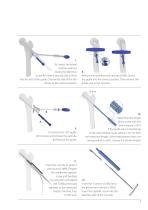
7. To correct the lateral position without losing the reference in the AP, insert a second wire (SI 952) into the slot of the guide. Choose the side of the slot closest to the correct position. Remove the wire from the cannula (S186). Orient the guide into the correct position. Then reinsert the guide wire in the cannula. To remove the 130° guide: (A) Unscrew and remove the cannula. (B) Remove the guide. 10. Determine the length of the screw with the wire measure (S187). If the guide wire is inserted up to the subchondral tissue, subtract 10 mm from the measured length. If the measurement...
Open the catalog to page 7
Anteversa® procedure 13. Insert the cannula into the previouslydrilled site. Tighten the screw, stopping before the chosen notch. 14. Inserting the screw only partially will facilitate insertion of the tube plate. 15. Assemble the plate Anteversa® and the introducer (S181 L o S182 R), insert the screw, insert the cannula (S1849), use the screwdriver (S540) to secure the instrument. 16. Introducing the plate using the guide wire will facilitate insertion onto the cephalic screws. 17. Remove the wire from the cephalic screw, align the plate on the shaft. Remove the T-handle (S140). 8 18....
Open the catalog to page 8
19. Remove the graduated drill guide, rotating it clockwise, and insert the screw with the screwdriver (S540). After that remove the introducer. Use the drill guide to make the other diaphyseal holes and tighten the remaining screws. 20. To adjust the position of the screw, insert the wire (SI 952) into the cephalic screw. Advance the screw to the desired position using the cannulated t-wrench (SI 892). 21. To use the compressor (SI89), screw the tie rod (A) to the cephalic 22. Turn the ring (B) clockwise to retrieve the fragment. To remove the compressor, turn the ring in the opposite...
Open the catalog to page 9
Anteversa® procedure 26. Remove the cannula (S1844) and insert the anti-rotation screw. Use an anti-rotation screw 10 mm shorter than the measurement of the cephalic screw (e.g., Cephalic screw = 100 mm, anti-rotation screw = 80 mm). 25. Drill holes with the graduated drill bit Ø 4 mm (S197) to the correct depth, and read the length on the graduated scale. 27. If necessary, screw on the cap to limit sliding of the cephalic screw. POST 30 DAYS CHECK Remove the diaphyseal screws and anti-rotation pin with a screwdriver (S540). Remove the plate. To remove the cephalic screw, use the cannulated...
Open the catalog to page 10
Ref. Implantes L. mm Locked Free Cannulated cephalic Anti-rotation pin screw 0 7 mm Ref. L. mm Ref. L. mm S1843 Anti-rotation nail drill guide 1 S1844 Drill guide cannula 1 S1847 Pin for anti-rotation drill guide 1 S186 Guide wire cannula 1 S1889 Cannula to protect the tissues 1 S1890 T-wrench for cephalic screw 1 S181C Anteversa® Introducer - grano 2 S193 Graduated drill guide 1 S1952 Kirshner Guide wire 0 2.7 mm, Material Implantes: Stainless steel AISI 316 LVM - ISO 5832-1 Cannulated cephalic screw and anti-rotation pin: AISI 316 LVM - ISO 5832-1 Screws and diaphyseal bushing: Titanium...
Open the catalog to page 11All Intrauma catalogs and technical brochures
-
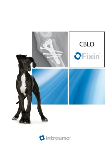
CBLO
4 Pages
-
TPLO
16 Pages
-
DPO
8 Pages
-
MicroCatalog
8 Pages
-
ELOS
20 Pages
-
FixinCatalog
44 Pages
-
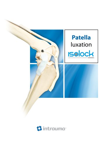
ISOLOCK
12 Pages
-
ISOLOCKPatellaProcedure
12 Pages
-
Isolock CrCL Procedure
8 Pages
-
PFF
8 Pages
-
Elafix
16 Pages
-
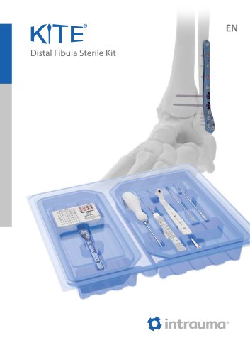
KITE
8 Pages


